Individual Assignment
Group Assignment
Table of Contents
Hero Shot
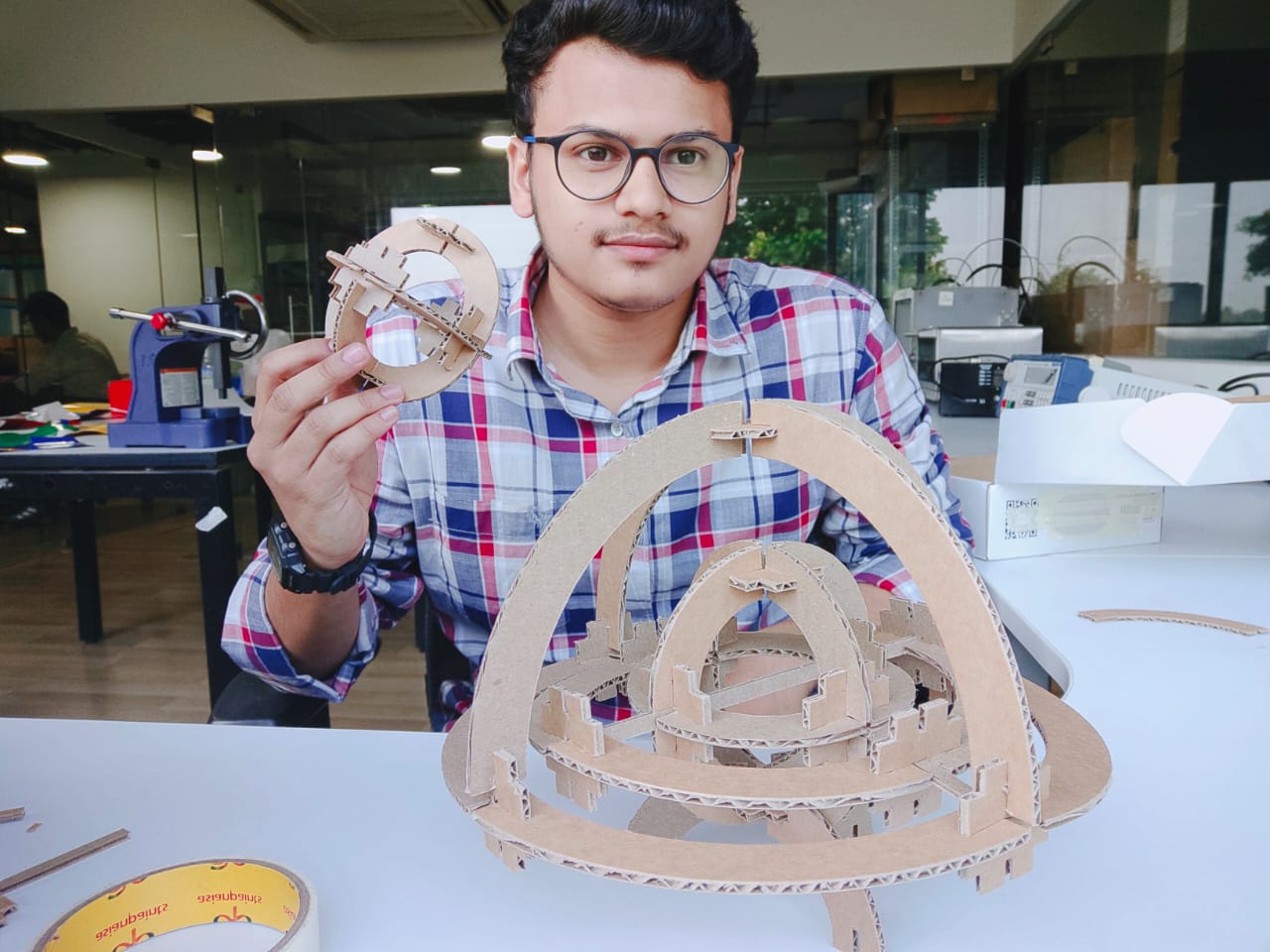
Group Assignment Result

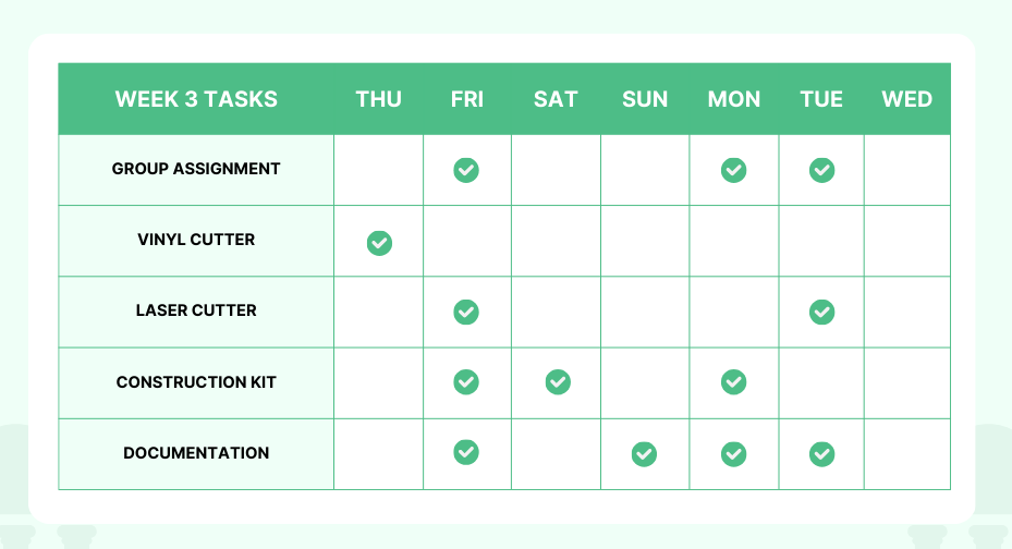
Week 3 Work Plan
Group Work
The week 3 group assignment is to characterize our laser cutter's focus, power, speed, rate, kerf, joint clearance, types, and document the work. The task of documenting the group assignment for this week was assigned to me and Kalyani.
Suresh Indu Laser (AccuCut 1325)
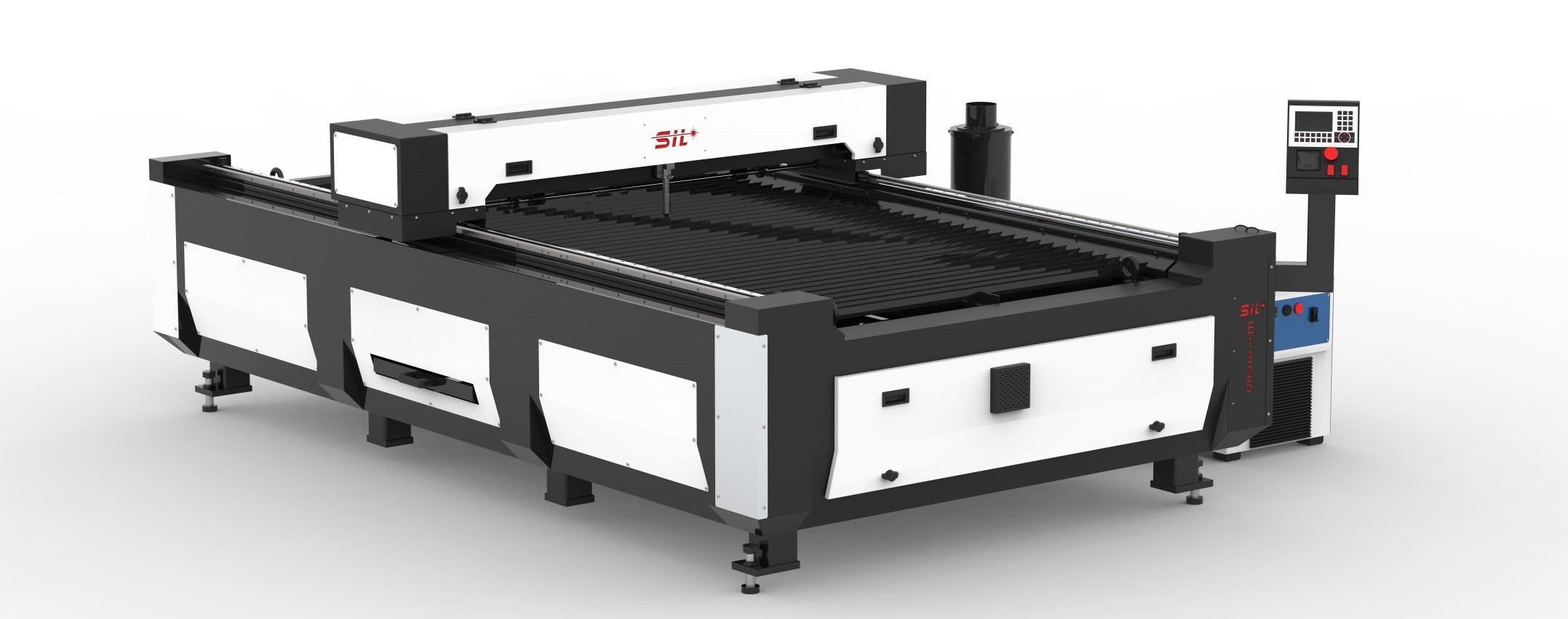
The SIL laser engraving machine is versatile and finds application in signage, indoor and outdoor advertising, art and craft, gifts, shoes, toys, garments, model cutting, papers and packaging, the wood and MDF cutting industry, interiors, decorators, and many more. SIL-built laser engraver, which is engineered and manufactured in India. SIL laser systems can be configured with two types of lasers: glass tubes and metal tubes.
Kerf of the laser cutter
Laser cutting is a kind of burning process. Thus, when a material is burned, it melts and shrinks, causing a material loss effect on the cutting material. The outcome will be impacted by this phenomenon. Therefore, we need to make adjustments to the design's loose measures, or what's known as the kerf.
- LaserCAD is the software used to operate this laser machine (Suresh Indu Laser).
- Open laserCAD from file open the desired file in DXF.
- From Layer Properties Select the outline colour to cut and select the work mode as cut". In our case, we chose "red”.
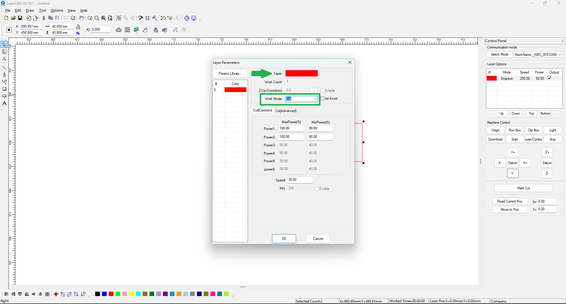
- Double-click the “cut” from the “layer option” and set the power and speed.
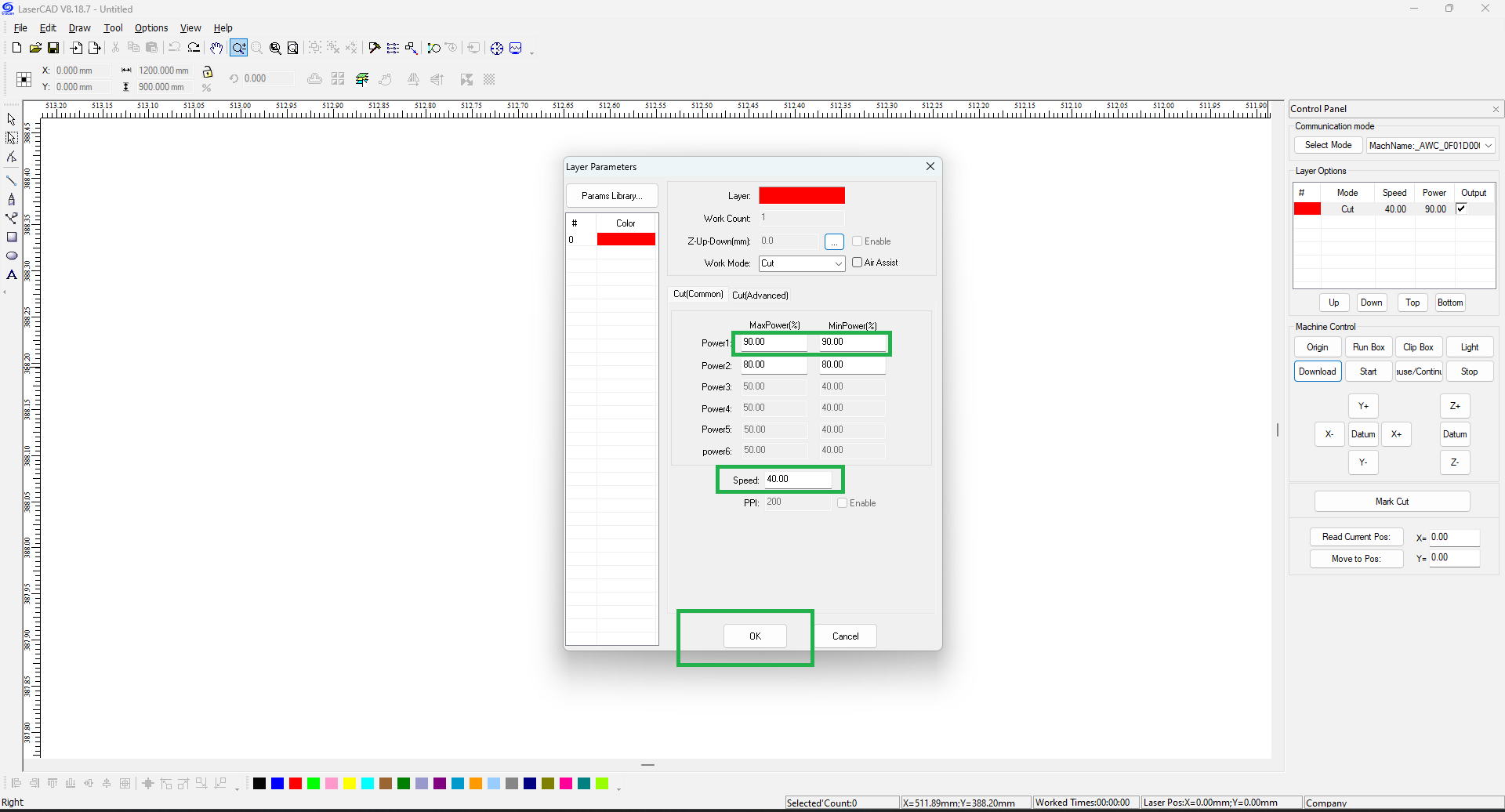
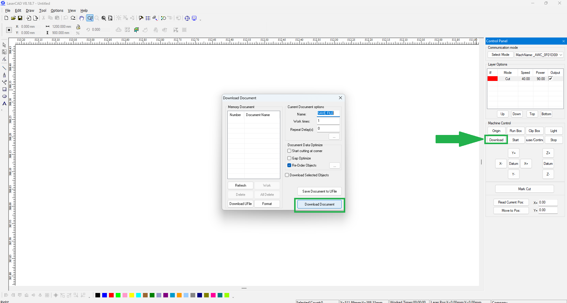
- Click “download” and then “download document” to send the file to the machine.
- The photo below depicts the thickness, power, speed, and kerf of cardboard, birch wood, and acrylic.
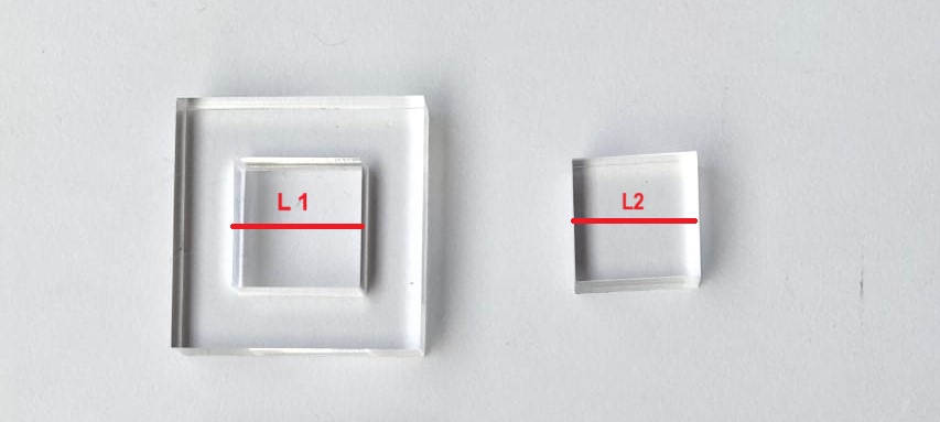
- Measure L1 and L2 for cardboard, wood, and acrylic using a digital vernier calliper.
- Kerf = (L1-L2)/2
- The photos below show the measurements of the outer square’s inner length and the inside square’s outer length of cardboard, wood, and acrylic.
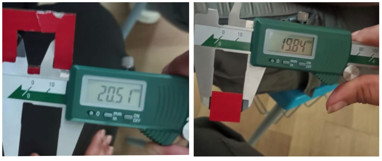
- 3.16 mm Cardboard
Total kerf = 20.51 - 19.84 =0.67 mm
Kerf= 0.67/2 = 0.33 mm
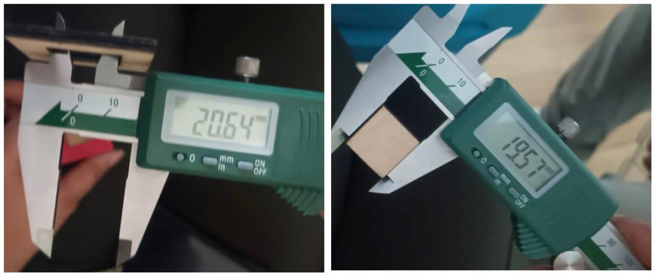
- 3.69 mm Birch Wood
Total kerf = 20.64 - 19.57 =1.07 mm
Kerf= 1.07/2 = 0.53 mm
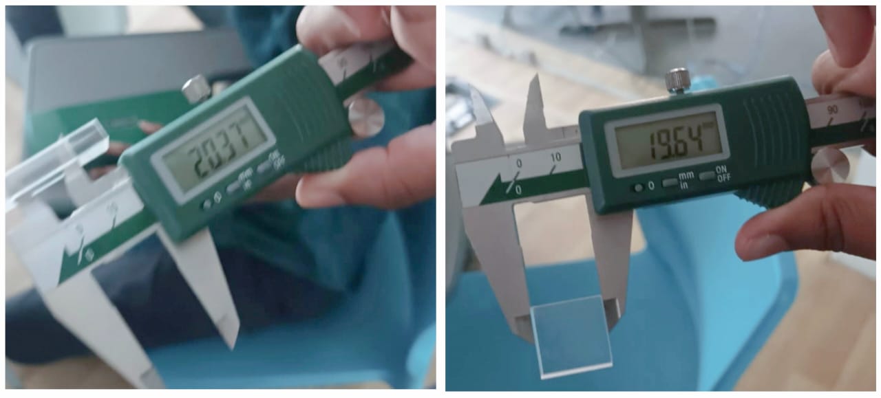
- 5.35 mm Clear Acrylic
Total kerf = 20.37 - 19.64 =0.73 mm
Kerf= 0.73/2 = 0.36 mm
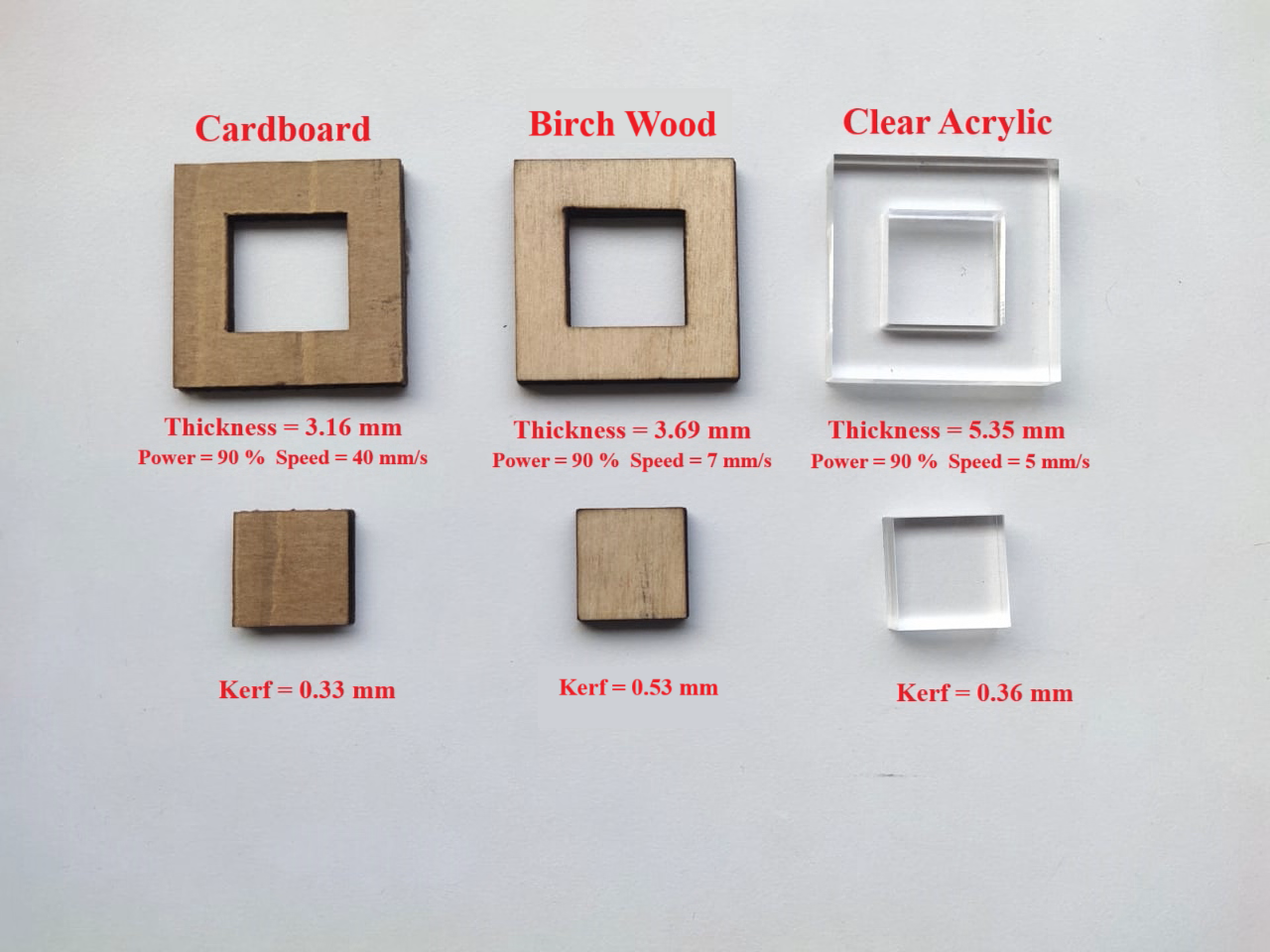
- The material, power, velocity, and laser machine will all affect the kerf value. Each material has a varied cutting power based on the materials listed below.
Cutting and Kerf Details
| Material | Cardboard | Birch Wood | Acrylic |
| Thickness | 3.16 mm | 3.69 mm | 5.35 mm |
| Power | 90% | 90% | 90% |
| Speed | 40 mm/s | 7 mm/s | 5 mm/s |
| Kerf | 0.33 mm | 0.53 mm | 0.36 mm |
Press Fit Test
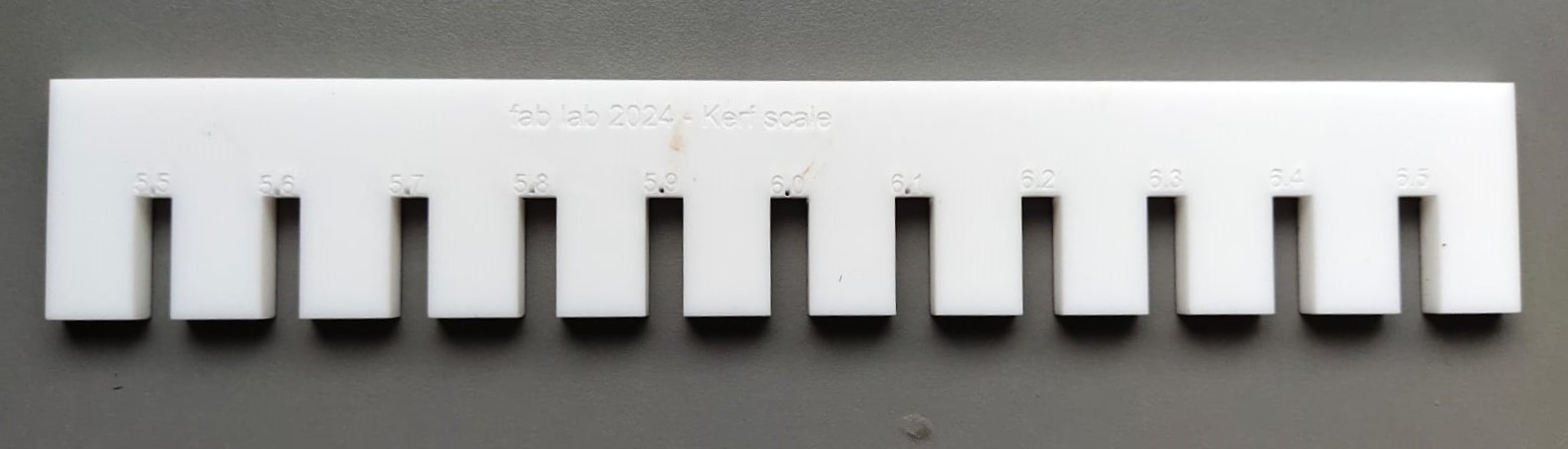
- Understanding the press fit tolerances of each material is helpful for creating high-quality laser joins. We created a test comb in Fusion 360 to verify it, and used Suresh Indu laser cutter to cut it out.
- The scale has slots with slot widths ranging from 5.5mm to 6.5mm, and then we exported the dxf file to Inkscape for cutting.
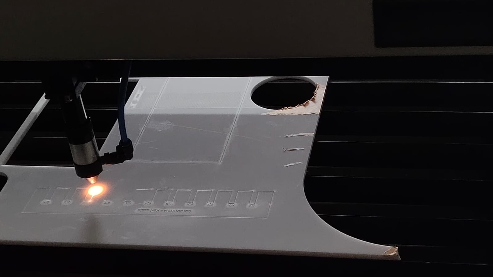
- The below image was taken during the laser cutting process.
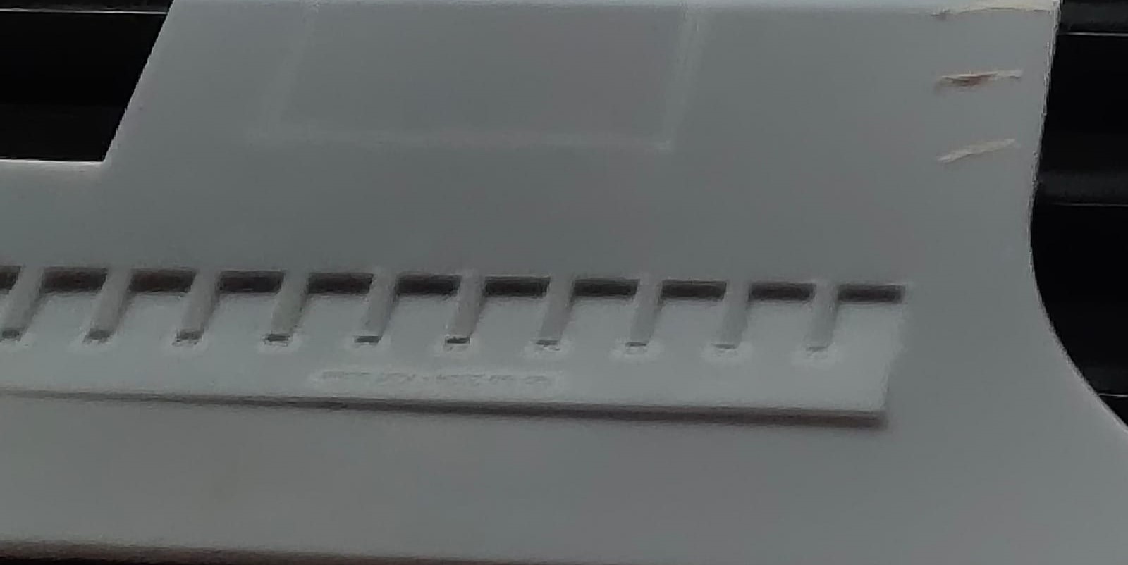
- The below image was taken just after the laser cutting process.
- Once the laser cutter completed cutting the comb, we used a red permanent marker to highlight the markings on the kerf scale.
- The below photos depict the measurements of the slot and the acrylic sheet using a digital vernier caliper.
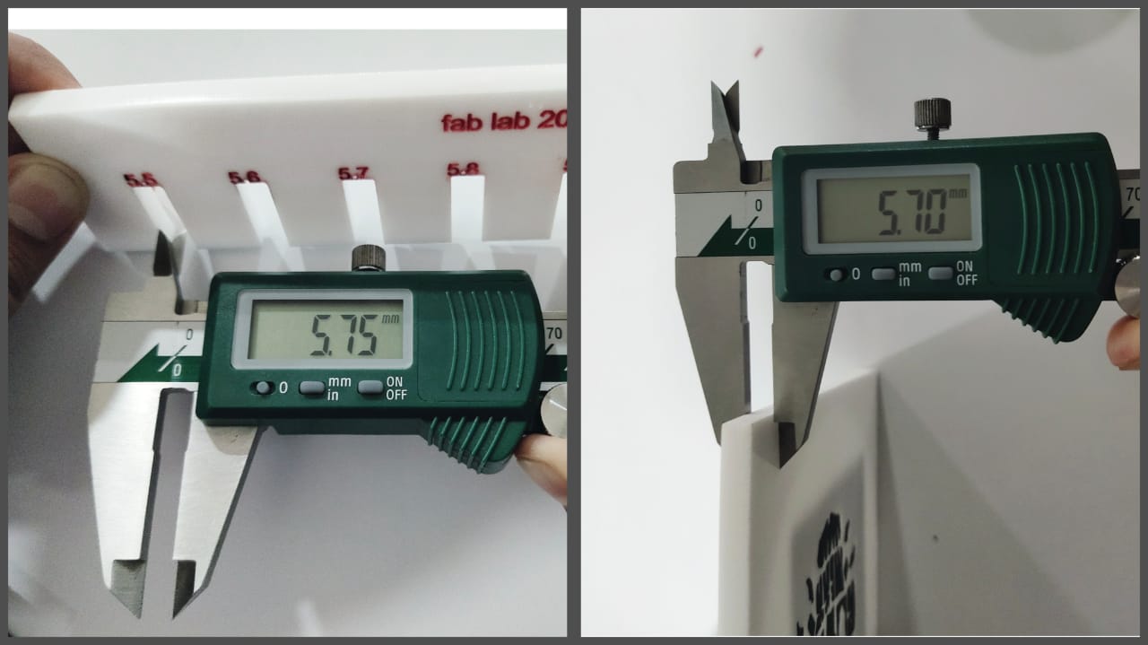
- After laser cutting, we got a perfect fit of 5.7 mm acrylic sheet in the 5.5 mm slot.
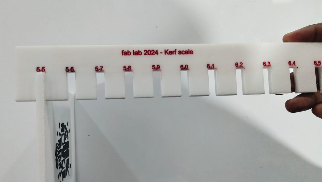
- The thickness of the acrylic sheet was around 5.7 mm, and we got a perfect fit in the 5.5 mm slot.
- Power= 100 %
- Velocity= 10 mm/s
- Therefore,
Kerf = (5.7 mm - 5.5 mm) = 0.2 mm
Joint Clearance = (kerf/2) = 0.1 mm
Vinyl
Polyvinyl chloride is the world's third-most widely produced synthetic polymer of plastic. It is a type of plastic which is made from ethylene (found in crude oil) and chlorine (found in regular salt). When processed, both substances are combined to form Polyvinyl Chloride (PVC) resin, or as is commonly referred to – Vinyl. Vinyl is a strong plastic that can be bent and used for making floor coverings, furniture, clothing, etc.
Self-adhesive Vinyl
Self-adhesive vinyl is a flexible and adaptable material used to create eye-catching signs and logos for both commercial and non-commercial purposes. It can be used to decorate walls, windows and other elements of a home or office and produce interior and outdoor graphics for advertising.
- Self-adhesive vinyl is an adhesive material used in various crafting and DIY projects. It is typically made of a thin, flexible vinyl film with pressure-sensitive adhesive backing. This allows it to be easily cut and applied to a variety of surfaces, including wood, metal, glass and plastic.
How do you use self-adhesive vinyl?
There are two ways to apply self-adhesive vinyl:
- Permanent method
This involves using an iron to heat the material and then applying it to whatever surface you want. The heat of the iron will activate the adhesive and make it stick permanently.
- Temporary method
This involves applying transfer tape over the design, pressing it down firmly onto your surface, pulling up one side of the transfer tape and then peeling off any remaining bits after five minutes. This creates a removable sticker with no glue residue on your surface.
Heat Transfer Vinyl
- Heat Transfer Vinyl (or HTV) is a type of craft vinyl that is often used on T-Shirts and fabrics through a heat-application process.
- This also commonly referred to as "iron-on" vinyl by most beginners. Popular types of Heat transfer vinyl include Siser EasyWeed, Premium Plus, Glitter, and Inkjet Printable. Many who work with this type of vinyl use a Cricut machine, weeding tools, and a heat press to bring their designs to life.
- One characteristic of HTV is that each sheet (or roll) of HTV comes with a carrier sheet which allows you to transfer your cut-out design to the shirt or fabric of your choice. This carrier sheet is often clear or frosty, and most importantly, the vinyl underneath is NOT sticky
Conductive Adhesive Vinyl
- Conductive adhesive vinyl is a type of vinyl material that has conductive properties, meaning it can conduct electricity.
- This material is often used in electronic and electrical applications where a flexible and adhesive conductive surface is needed.
- The adhesive backing allows it to be easily applied to various surfaces, making it suitable for various projects.
- Applications for conductive adhesive vinyl include creating flexible circuits, repairing or adding conductivity to electronic devices, and prototyping electrical components. It's particularly useful in situations where traditional rigid circuit boards may not be suitable due to size or flexibility requirements.
Vinyl Cutter
A vinyl cutter, also known as a plotter or cutting plotter, is a computer-controlled machine that has a controllable pen knife used for cutting various materials, primarily vinyl sheets.
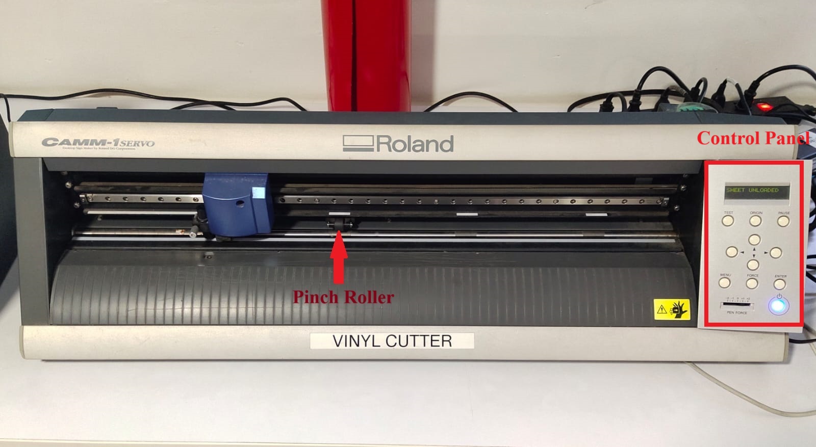
Roland GX-24 Vinyl cutter machine
The Roland GX-24 is a vinyl cutter/plotter that can create graphics like decals, stickers, labels, signage, stencils, pin striping, vehicle graphics, and window tint. It has features for speed, performance, reliability, precision, and handling.
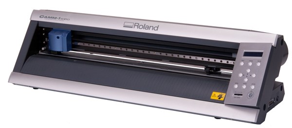
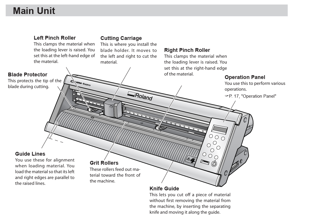
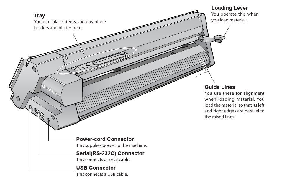
The Roland GX-24 machine's component details are displayed in the image below. It's a high-speed device driven by servo motors.
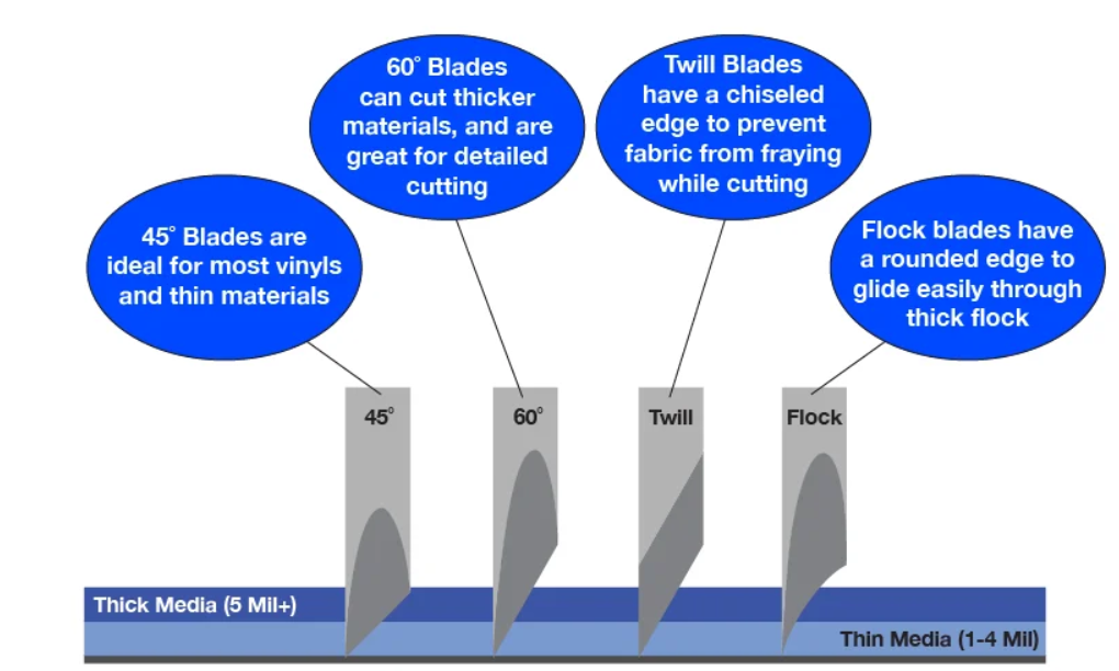
The blades have a 45-degree angle to the cutting direction, making them extremely sharp and pointed. We utilize 45° cutting angle blades in Fab, but there are additional blades available at 30° and 60° cutting angles.
Basic overview of how a vinyl cutter works:
- Design Creation: Users create a design on a computer using graphic design software. The design is typically in vector format, which allows the cutter to accurately follow the paths.
- Material Loading: A roll or sheet of vinyl is loaded into the vinyl cutter. The machine typically has adjustable rollers to secure the material in place.
- Calibration: Before cutting, the vinyl cutter may need to be calibrated. This involves ensuring that the cutter recognizes the starting position and the size of the material to be cut.
- Software Setup: The design is then sent to the vinyl cutter's software, which translates the vector graphics into a series of cutting instructions. These instructions define the paths that the blade will follow to cut the vinyl material.
- Blade Movement: The vinyl cutter's blade is mounted on a carriage that can move along the X and Y axes. The blade is controlled by a motorized system that precisely moves it along the specified cutting paths.
- Blade Adjustment: The blade's depth and pressure are adjusted according to the material being cut. The blade should cut through the vinyl material but not through the backing, ensuring that the design remains intact.
- Cutting Process: The vinyl cutter's blade moves along the predefined paths, cutting through the vinyl material while leaving the backing material untouched. The movement of the blade is synchronized with the cutting instructions from the software.
- Weeding: After the cutting is complete, a process called "weeding" is done. This involves removing the excess vinyl material from around the cut shapes, leaving only the desired design on the backing.
- Transfer Tape: If the design needs to be transferred to another surface, a transfer tape is applied over the cut vinyl, allowing the entire design to be lifted off the backing and transferred to the desired surface.
Design Creation
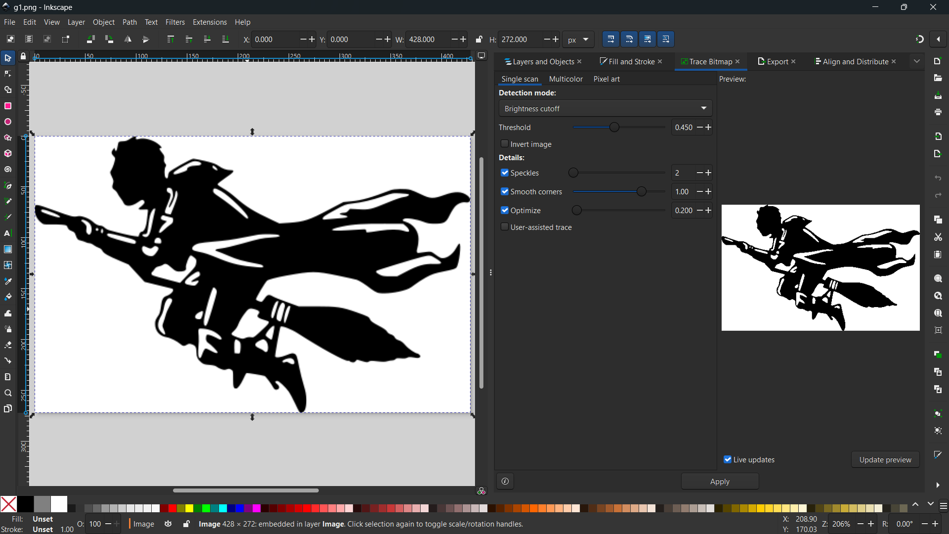
For the design creation, I used a robot logo and a Harry Potter logo. Initially, these logos were downloaded from the internet as raster images and converted into vectors using bitmap tracing in Inkscape.
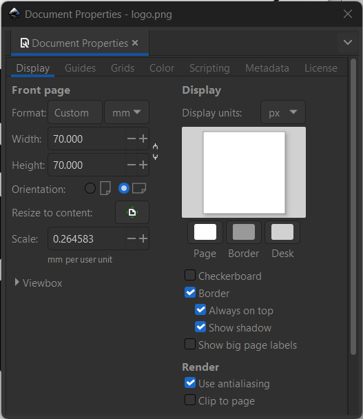
- The logo was imported into Inkscape and resized from the document properties.
- I used the "trace bitmap" feature to convert the raster image into a vector image.
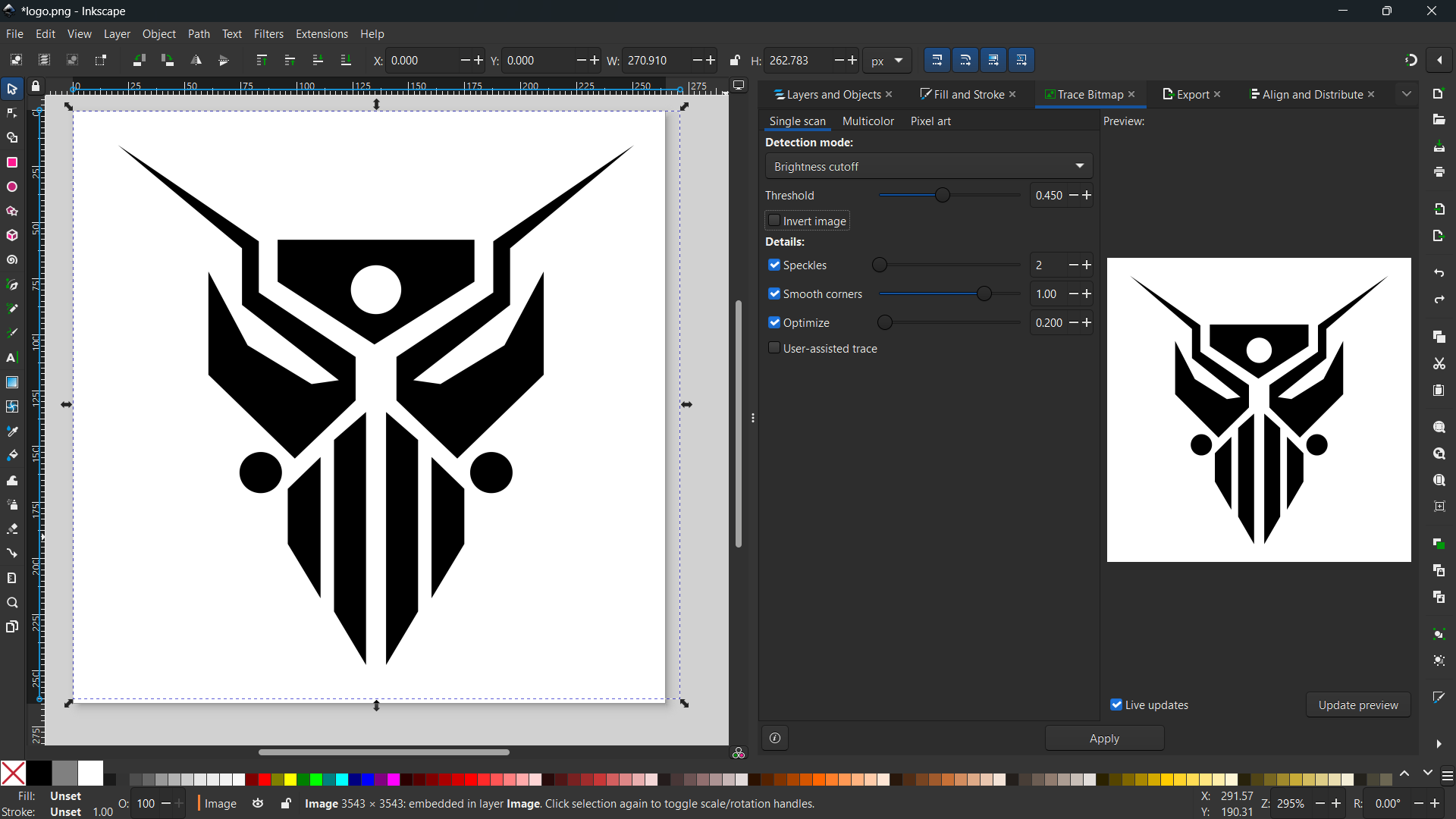
- The converted vector image was exported in the SVG file format.
- Similarly, the Harry Potter logo was imported into Inkscape, resized, and converted to a vector image. Finally, exported in SVG file format.
Machine Setup and Material Loading
- First, we load the sticker roll or sheet by lining up the paper and releasing the loading lever. After the vinyl paper has been aligned, we lock the sheet down to the cutter by pushing the loading lever and lining up the pinch rollers with the white lines.
- We can also mechanically alter the force and create a deeper cut by exposing more of the blade.
- Finally, from the vinyl cutter, choose an origin, and use the test button to create a test cut.
- There are different types of blades with different angles and shapes that are available for vinyl cutting. In our fablab, we used the blade at 45 degrees, which is ideal for thin material.
Software Setup [ Mods CE ]
Fab Mods is an open-source web app program that is used as machine software or a driver and works with web socket technology. The moderator replaces the window software with the machine, which provides the machine with the means to cut or mill the given image or vector file.
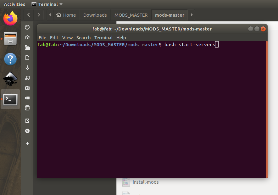
- Open the mods-master folder, right-click, and select “open terminal". From the terminal, type the following command:
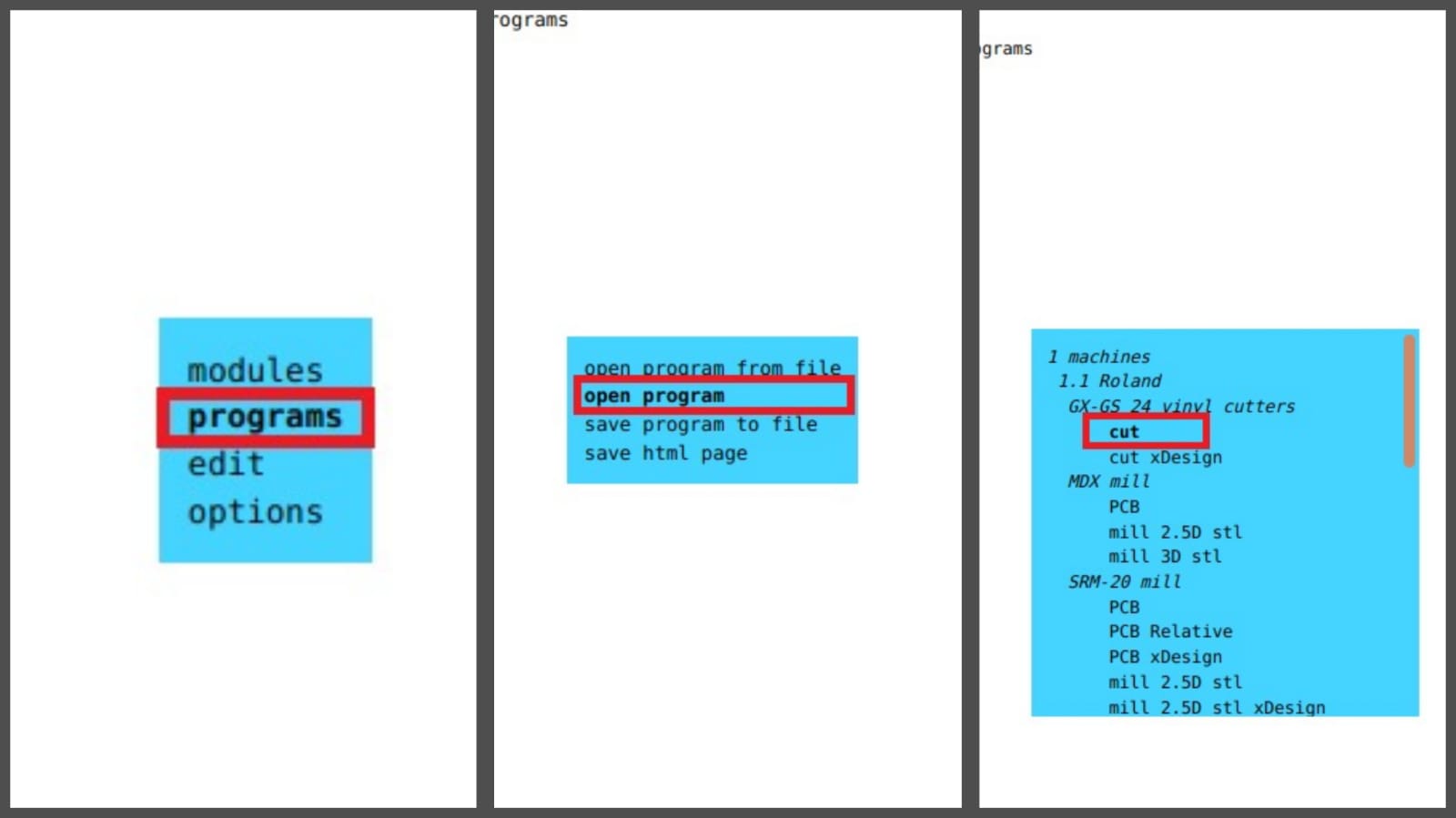
- Then right-click on the page and navigate to "programs" the select "open program" and select "GX-GS 24 vinyl cutters - cut".
- Once the Mods CE interface is open, open our file. If the file is in SVG, open it from the “read SVG tab”. If the file is in PNG, open it from the read PNG file.
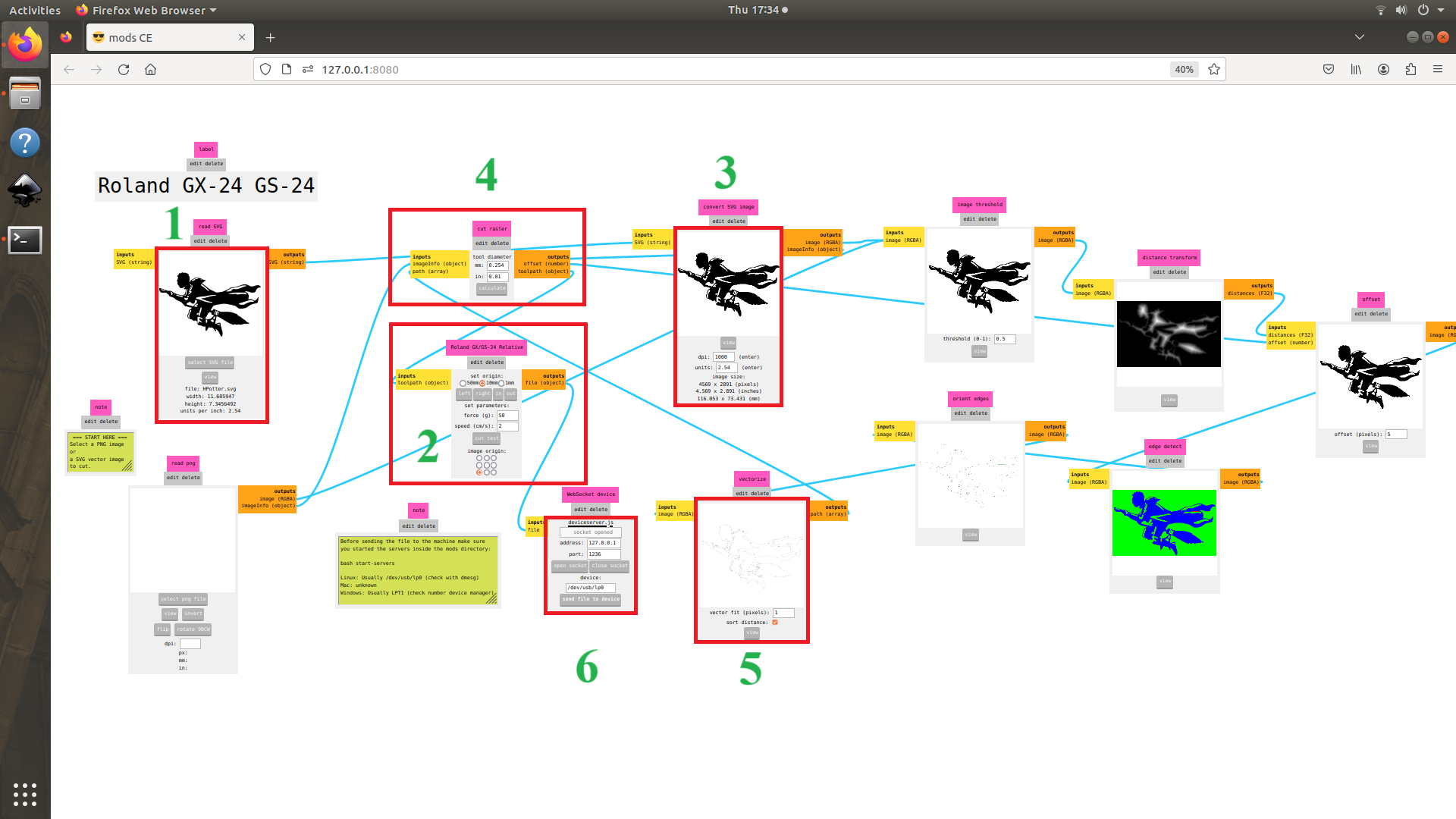
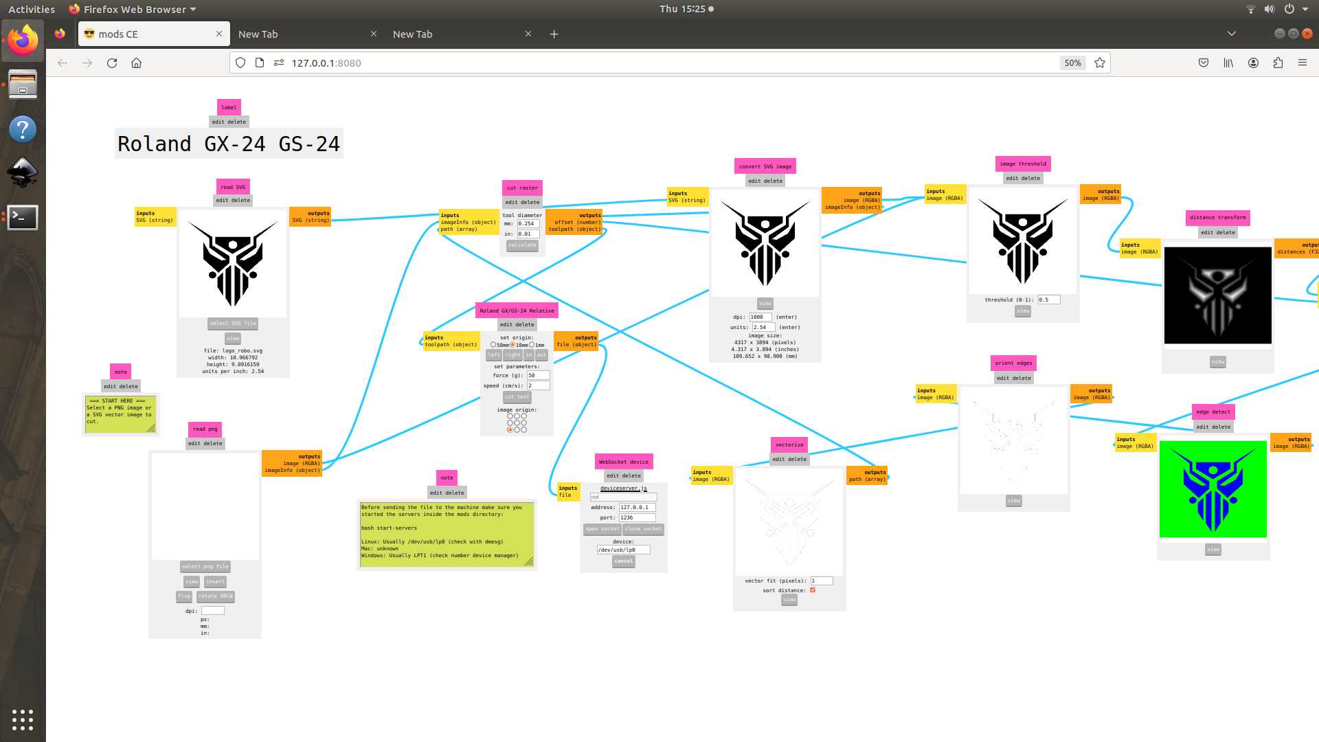
- Select the origin, based on how we set the viny in the cutter.
- Change the dpi to “1000”.
- Select the “calculate” button.
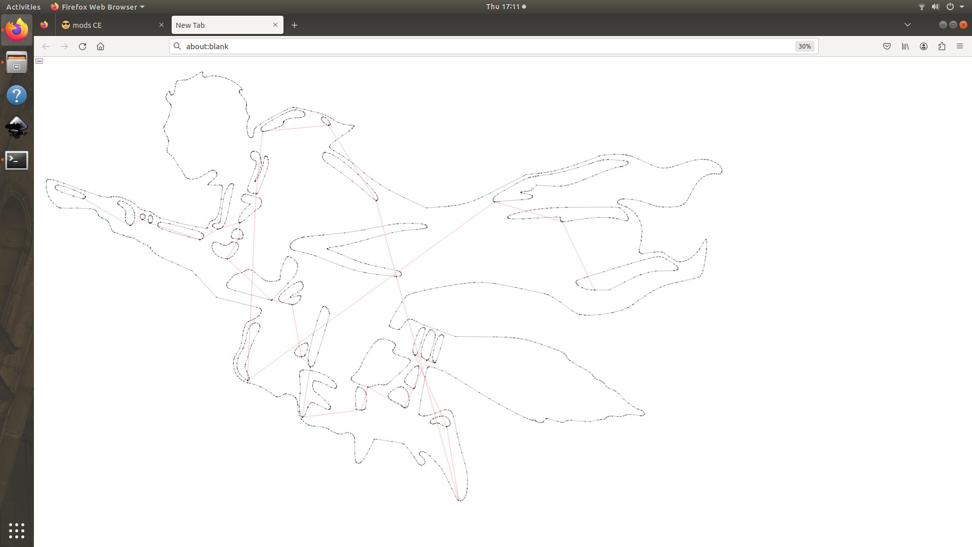
- View the path of our image from the “vectorize” box. Finally, select the “open socket” button and click the “send file to device” button.
Cutting Process
The vinyl cutter uses a tiny knife that is allowed to rotate on a free axis using a ball bearing.
- I first chose to put my robot logo and Harry Potter sticker on my laptop, but I later changed my mind and put the Harry Potter sticker on my water bottle.
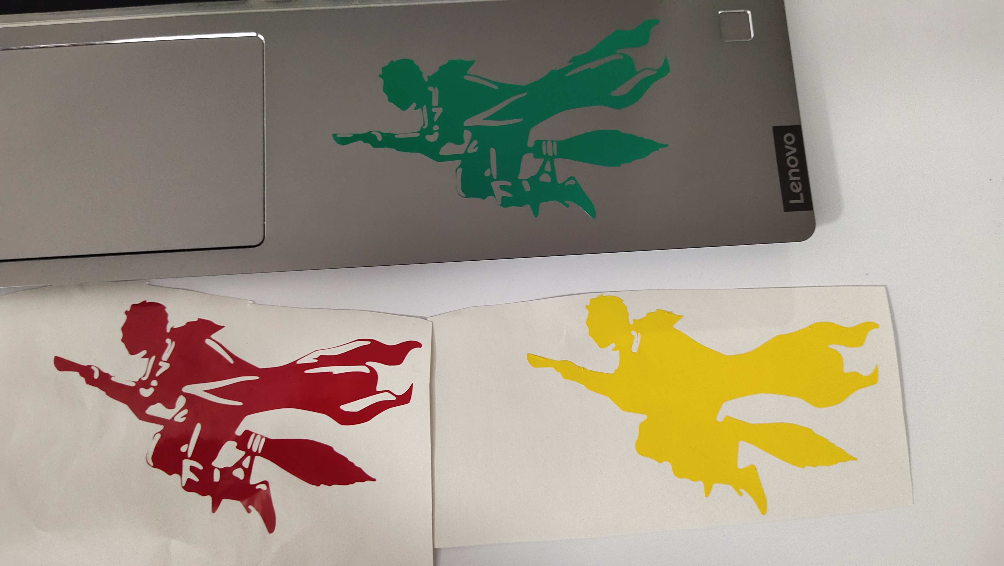
Final Result
- The final result of the robot logo.
- The final result of Harry Potter on my water bottle.
Laser Cutting
Laser cutting or Laser Beam Machining (LBM) is a manufacturing process that involves cutting through the material by focusing a high-energy laser. In other words, laser cutting involves cutting a workpiece by melting and evaporating the corresponding portions of material with a focused light beam that moves along a path provided by a CNC code.
LASER is an acronym for Light Amplification by Stimulated Emission of Radiation.
The process takes a series of steps that start with generating and programming the desired cutting pattern. From here, the machine is loaded with the program to begin cutting.
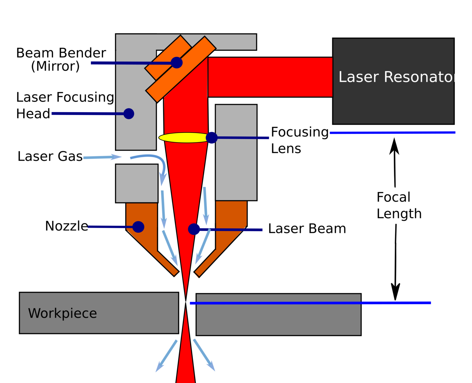
- Laser generation: The resonator receives energy from the power supply and generates the laser beam.
- Laser amplification: The two mirrors located at the ends of the head amplify the intensity of the laser beam by making it flow through the amplifying medium.
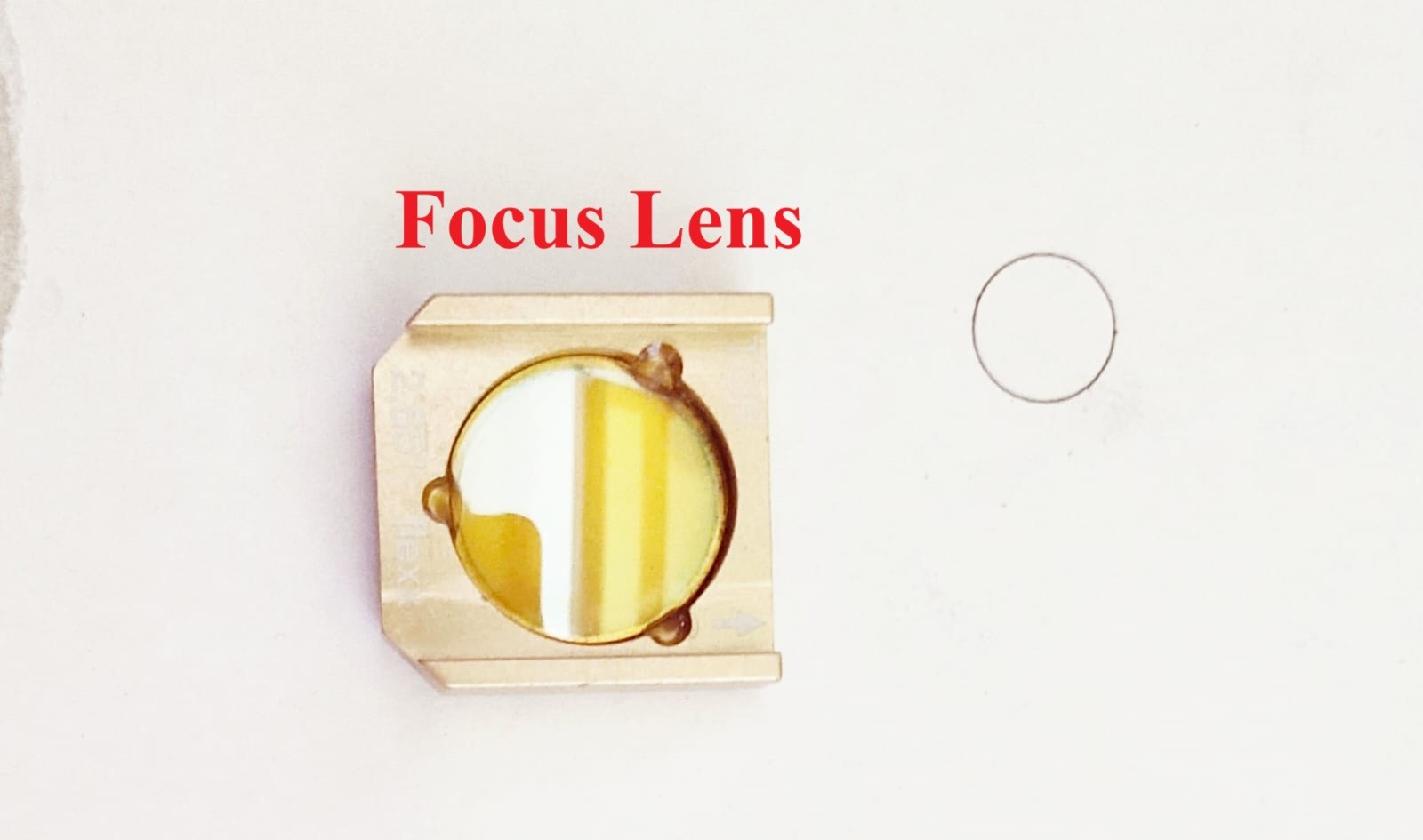
- Laser direction and focus: Depending on the type of laser cutting technology, a fibre optic cable or a group of mirrors in the focusing head give direction to the laser beam. Then, a lens achieves the energy focus required for the laser beam to be able to cut.
- Gas supply: The cutter blows gas through the nozzle to clear the molten from the kerf.
- Cutting: Once the head focuses the energy, the laser melts and evaporates the material. The movement of the cutting head occurs automatically along the pattern created in the CNC program, thus making the corresponding kerf. In some cases, the workpiece moves while the cutting head stays still.
Types of laser used in our lab
- CO2 Lasers: Manufacturers use Carbon Dioxide (CO2) lasers for cutting non-metallic materials like wood, acrylic, plastic, fabric, leather, and paper. If coated with a layer, the CO2 laser can cut metal to stop the reflection.
- Fibre Laser Cutting: Fibre lasers are ideal for cutting metals, ferrous metals like steel and non-ferrous metals like aluminium, copper, and brass. They are highly efficient and have a high cutting speed.
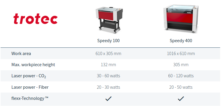
TROTEC Speedy100
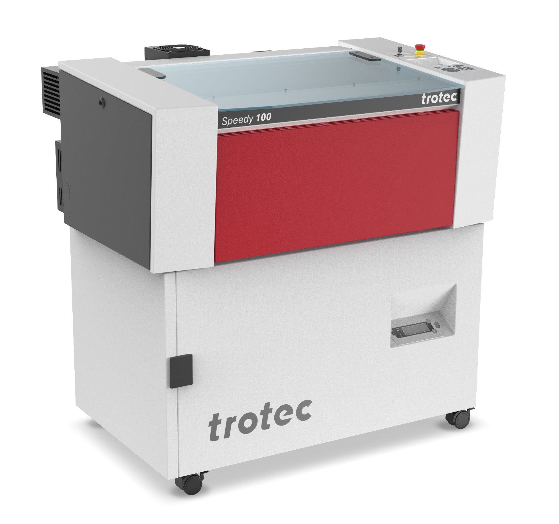
The TROTEC Speedy 100 is a laser engraving machine manufactured by TROTEC, a company that specializes in laser cutting and engraving technology. The Speedy 100 is a compact and versatile laser engraver designed for a variety of applications, including marking, engraving, and cutting various materials such as wood, acrylic, leather, and more.
TROTEC Speedy 400
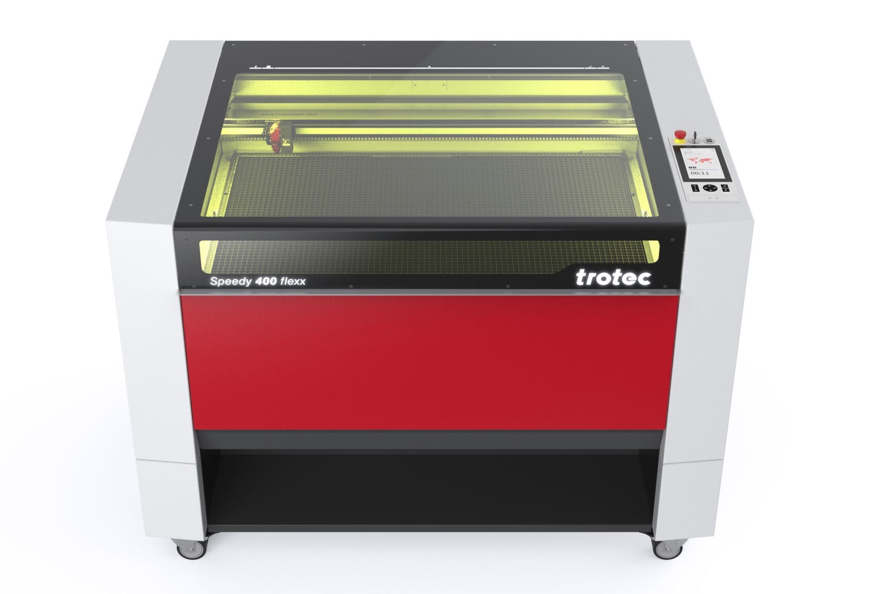
The Trotec Speedy 400 is a laser engraving and cutting machine manufactured by Trotec, a company known for producing laser equipment. The Speedy 400 is part of the Trotec Speedy series, which includes various models designed for different applications and workloads.
Key features of the Trotec Speedy 400 may include:
- The Speedy 400 is primarily used for laser engraving and cutting a variety of materials, including wood, acrylic, plastic, leather, and more.
- These machines are known for their high-speed engraving capabilities and precision, making them suitable for both intricate designs and large-scale projects.
- Trotec laser machines typically come with dedicated software for designing and controlling the laser engraving process.
- The Speedy 400 has a specific work area, which determines the maximum size of the material that can be engraved or cut.
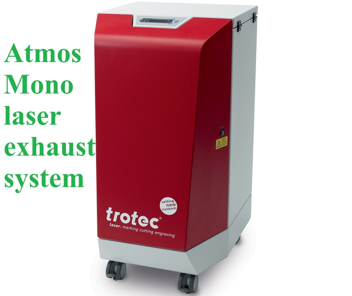
- Laser engraving produces fumes, and these machines often come with built-in exhaust and ventilation systems to ensure a safe working environment.
Machine Setup
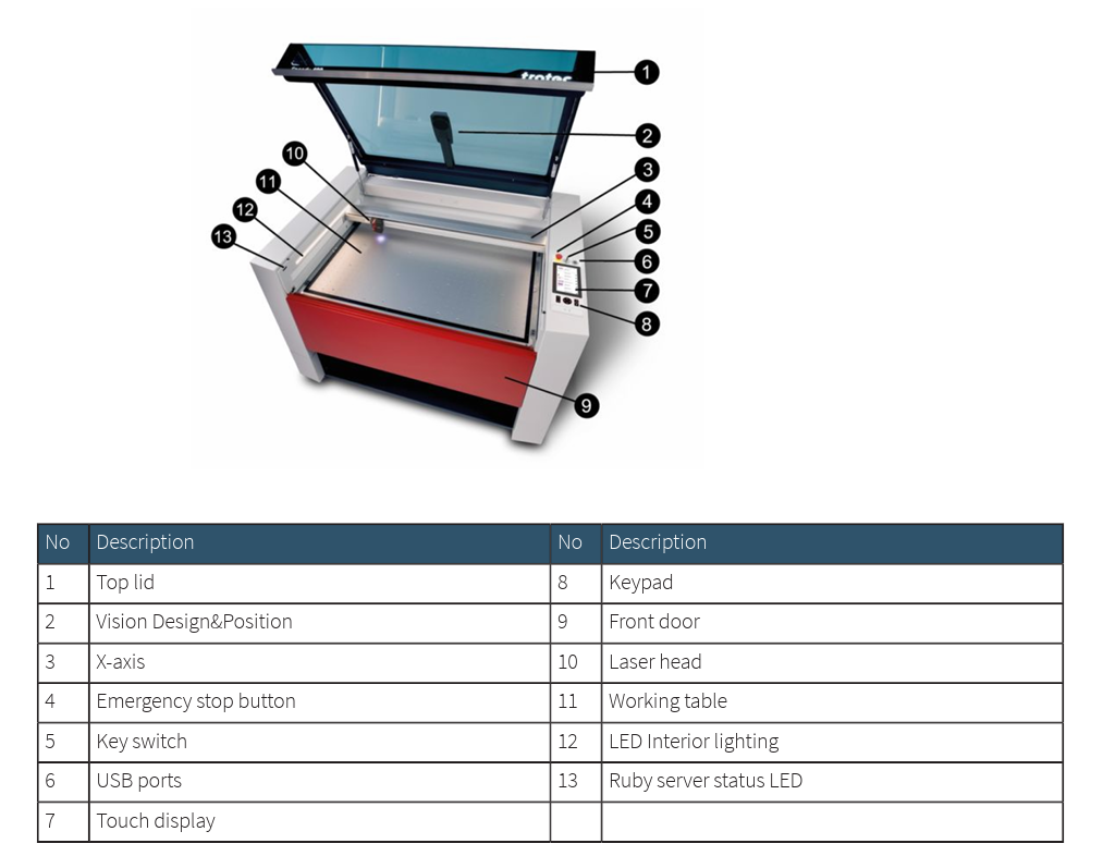
- To start the machine, turn on the power supply first, and then turn the knob to the right.
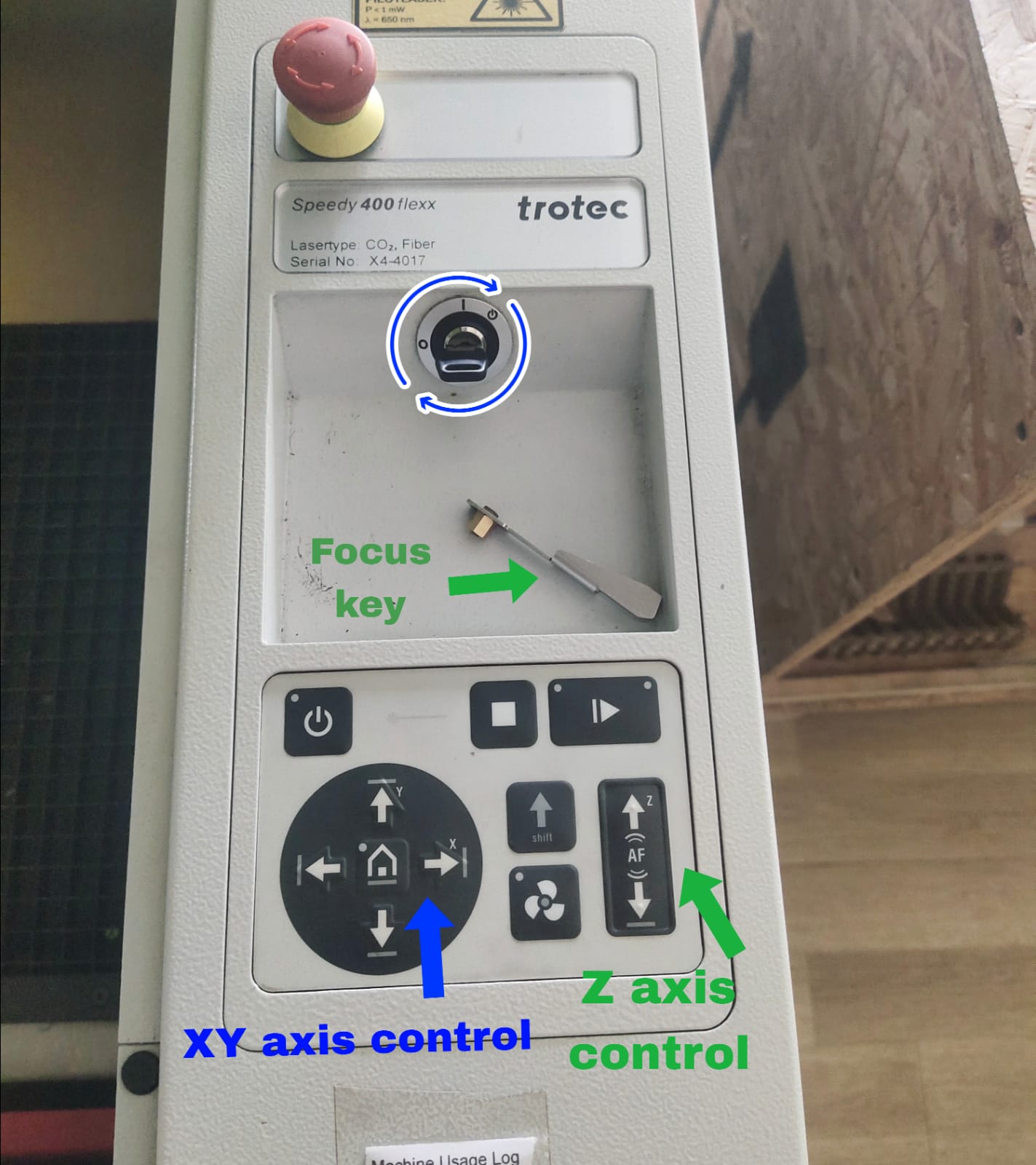
- Make sure the lid is closed. In the process of initialization. Wait for the laser to return home and listen for the beep. When the machine has finished calibrating and booting up, you can open the lid.
- After opening the lid, position the material in the workspace. It would be a good habit to position it at the workspace's upper left corner, or the origin (0,0).
- Use the arrows on the machine's interface to move the laser head. The up/down arrow keys with the z symbol on them can be used to manipulate the laser head in the z-axis.
- The z-axis setup is a crucial step in ensuring that the laser is properly focused. To allow the focus tool to float lightly, place its gold lip on the small ledge of the laser head. Then, move the bed in the z-axis until the focus key barely falls off the laser head.
- To auto-focus the laser head, press the up and down arrow keys (with the "Z" marking on top) at the same time from the machine panel.
- Make sure to activate the exhaust vents after adjusting the z-axis.
- Inkscape was used for the design. Ensure to resize the page to fit the content.
Software Setup
Trotec JobControl is a laser software that helps prepare graphics and text for laser engraving or cutting. It receives print jobs from image editing software and arranges them on the laser cutter's bed for cutting and engraving.
- If desired, you can use the coordinates in the job centre to move the laser head. To fully customize your work, you may change everything here, including the power, velocity, frequency (for engraving and cutting), material type, moving your design, moving the laser, and more.
- Open the menu, click on “Import from File”, and select the desired file.
- Once the file is selected, place the design in the coordinates to set the origin.
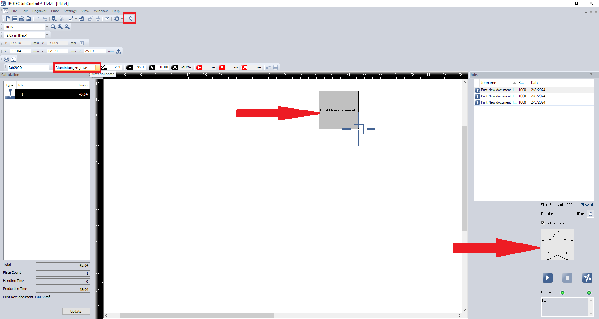
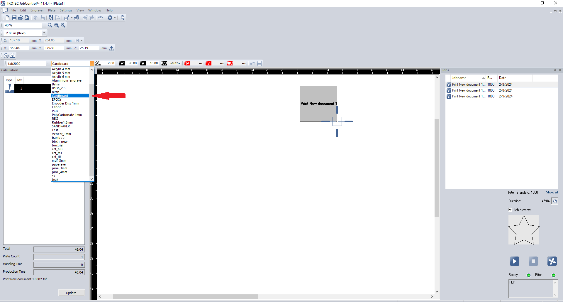
- From the material list, select our desired material. In our case, we used cardboard to test, so I selected "cardboard”.
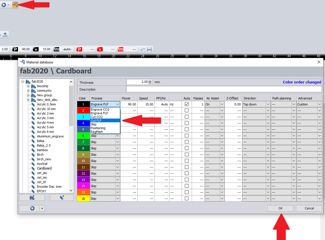
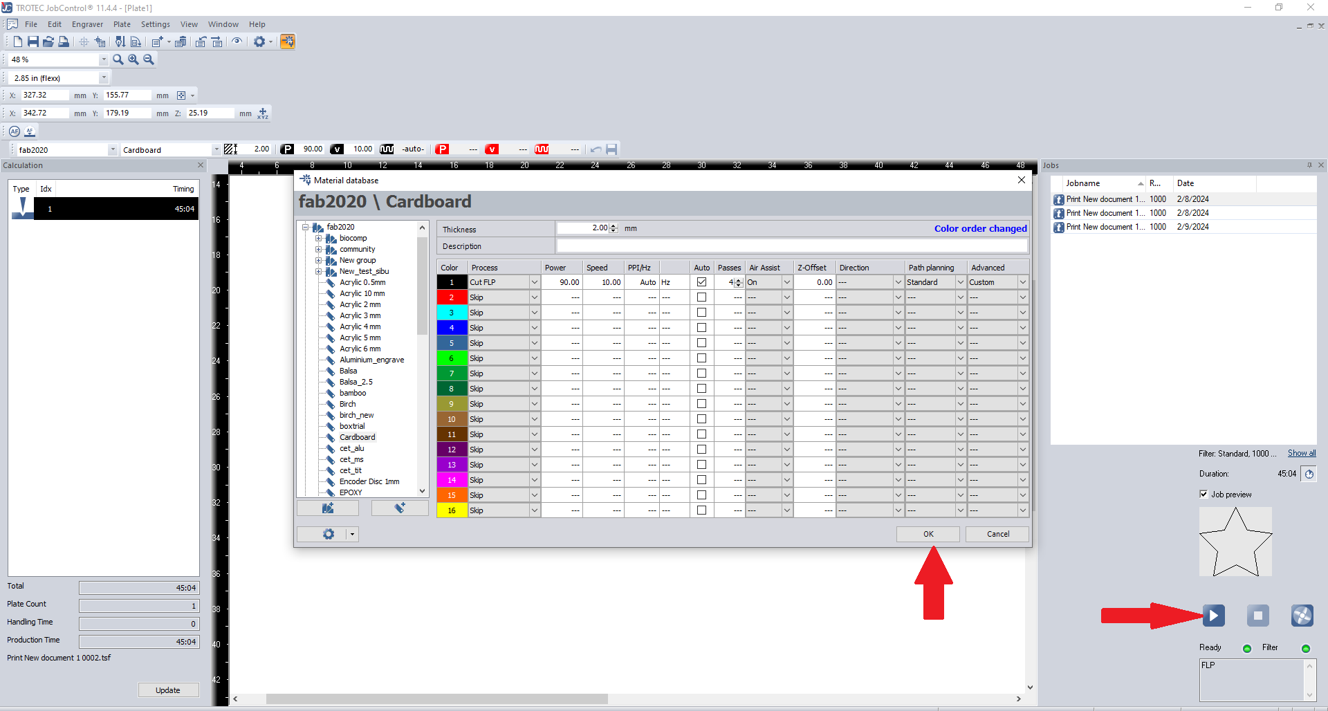
- Open the “material template” or press “Ctrl + M” and provide the required process for each colour in our design. For our case, we tried to cut first, so I selected “Cut FLP”.
- Once all the required processes are selected, press “Play” button to start the process.
- After the task is completed, make sure that the machine's lid remains closed for a few minutes to prevent any fumes or smells from escaping. When the task is finished, a display bar on the machine becomes green. The bar will flash yellow while it is active.
Parametric Construction Kit
Parametric design in Fusion 360 refers to the use of parameters to define and control the geometric and dimensional aspects of a 3D model.
I decided to use Fusion 360 to create a parametric construction kit. Fusion 360 provides parametric modelling tools that allow me to create designs that can be easily modified by changing parameters.
For the group project, we used Suresh Indu Laser. To prevent any harm to the machine, it is strongly advised that you remain vigilant and close to the laser. Since the Suresh Indu Laser is open, it emits a lot of smoke during cutting, and many of us experience suffocation when working on the group assignment, so our instructor decided to perform the cutting of the parametric construction kit on Zund.
First Attempt
- Open Fusion 360 and create a new design.
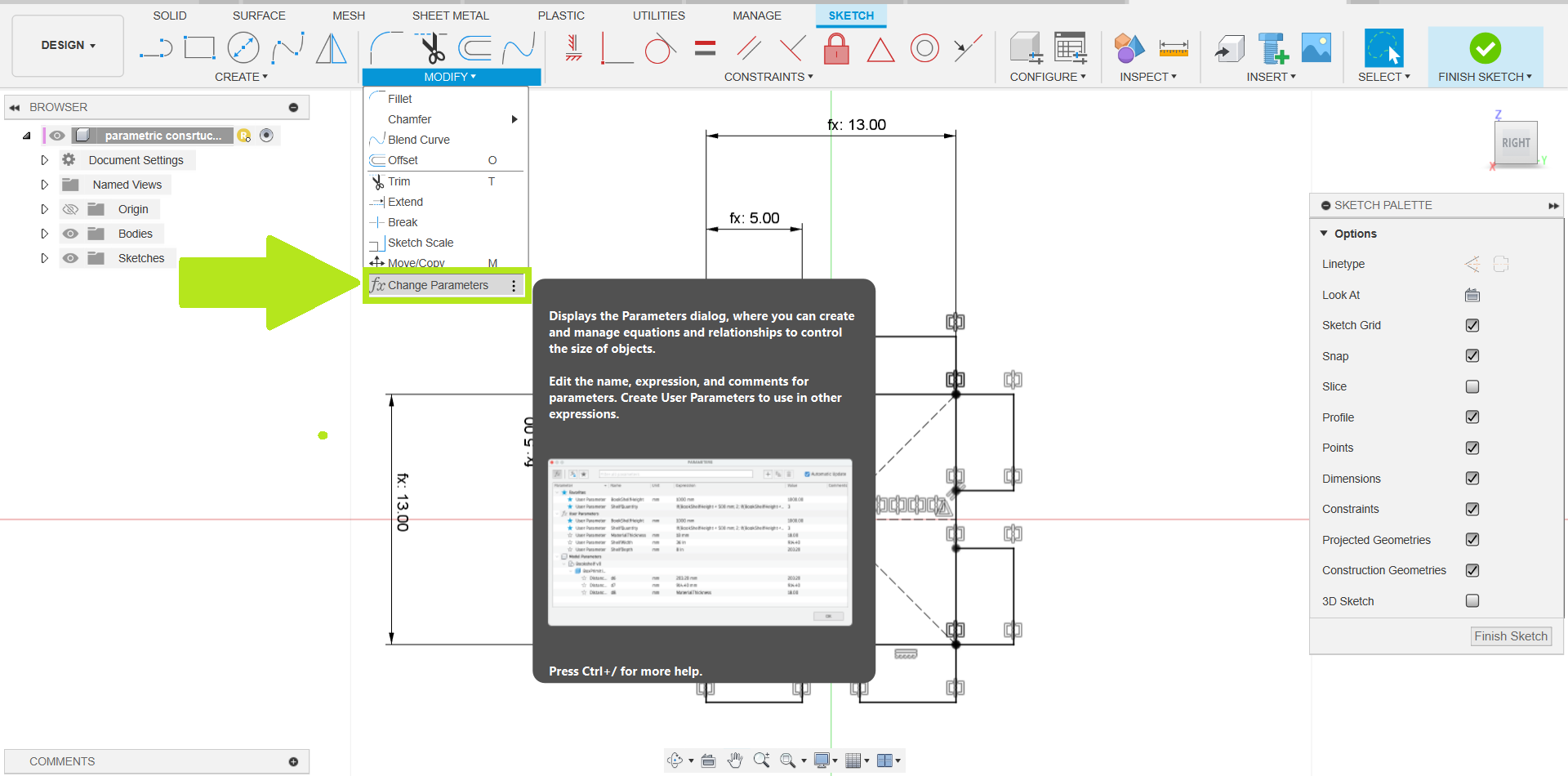
- Go to the "Modify" menu and select "Change Parameters”.
- Create parameters for dimensions that you want to be adjustable. For example, you might have parameters for length, width, height, etc.
- Start by creating a sketch on the desired plane.
- Use the sketch tools to draw the basic geometry of your construction kit component.
- Use maximum parameters to specify the sizes of various elements in your sketch.
- Apply geometric constraints to ensure that your sketch maintains its shape and proportions.
- Instead of entering fixed values for dimensions, use the parameters you created. This makes your design parametric.
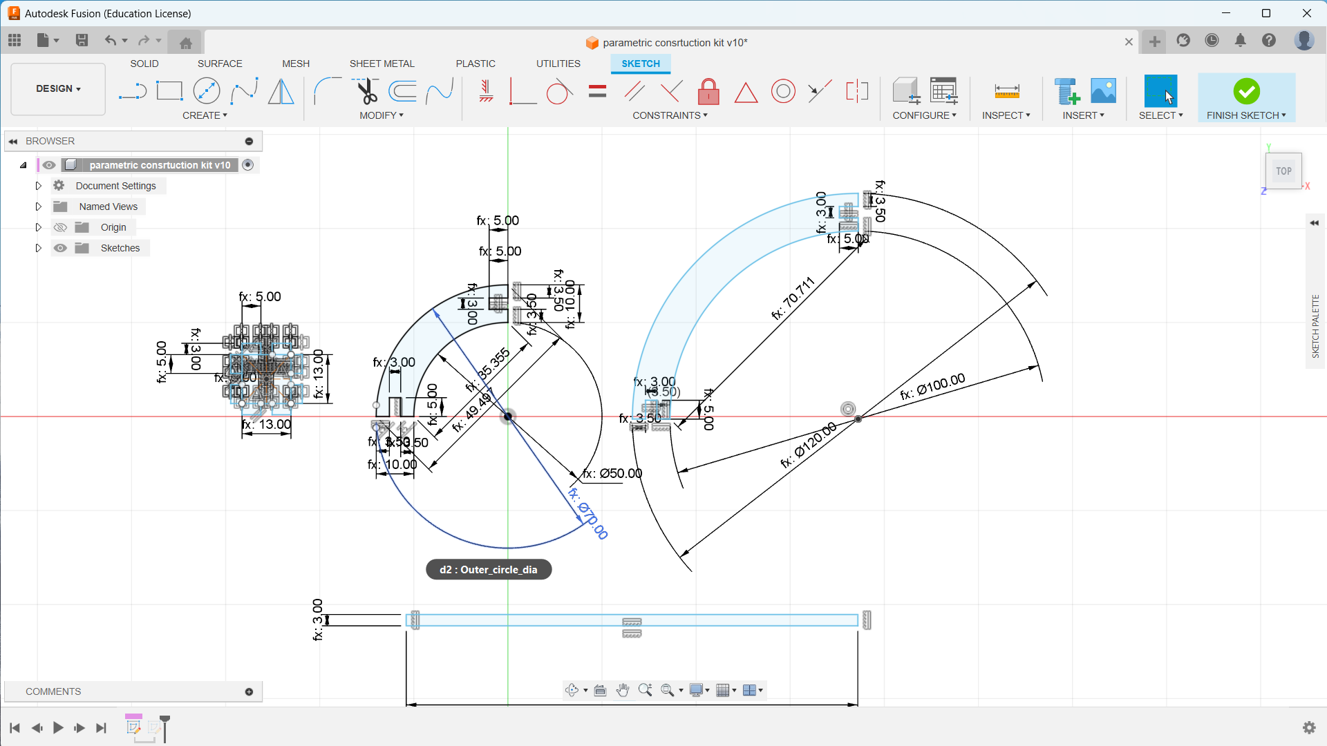
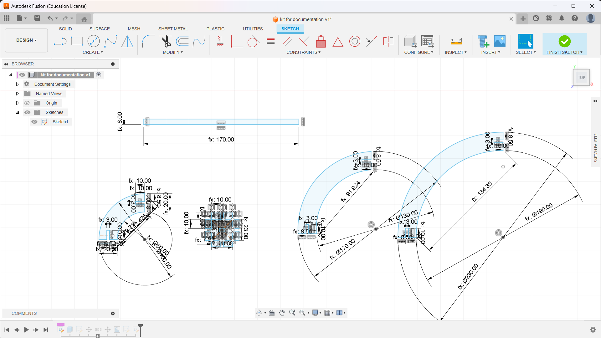
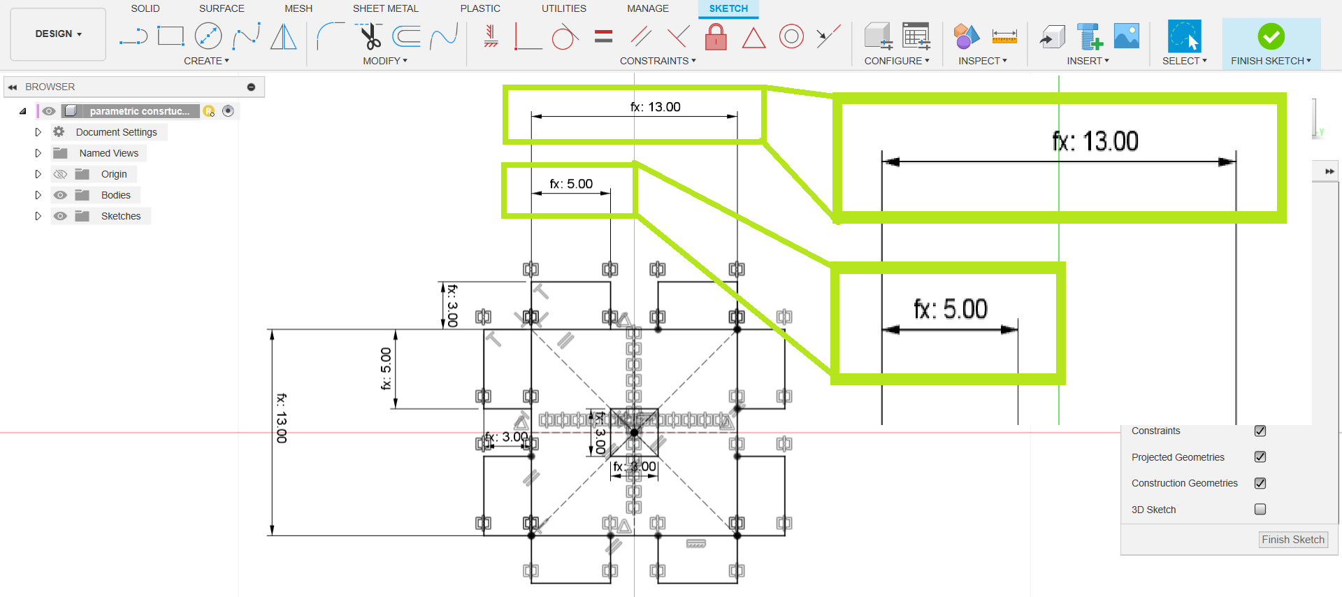
- The image shown below illustrates the basic geometry of my construction kit.
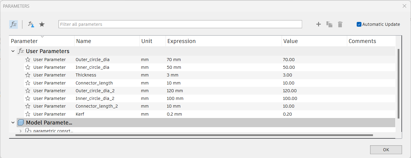
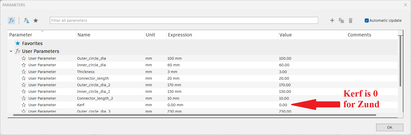
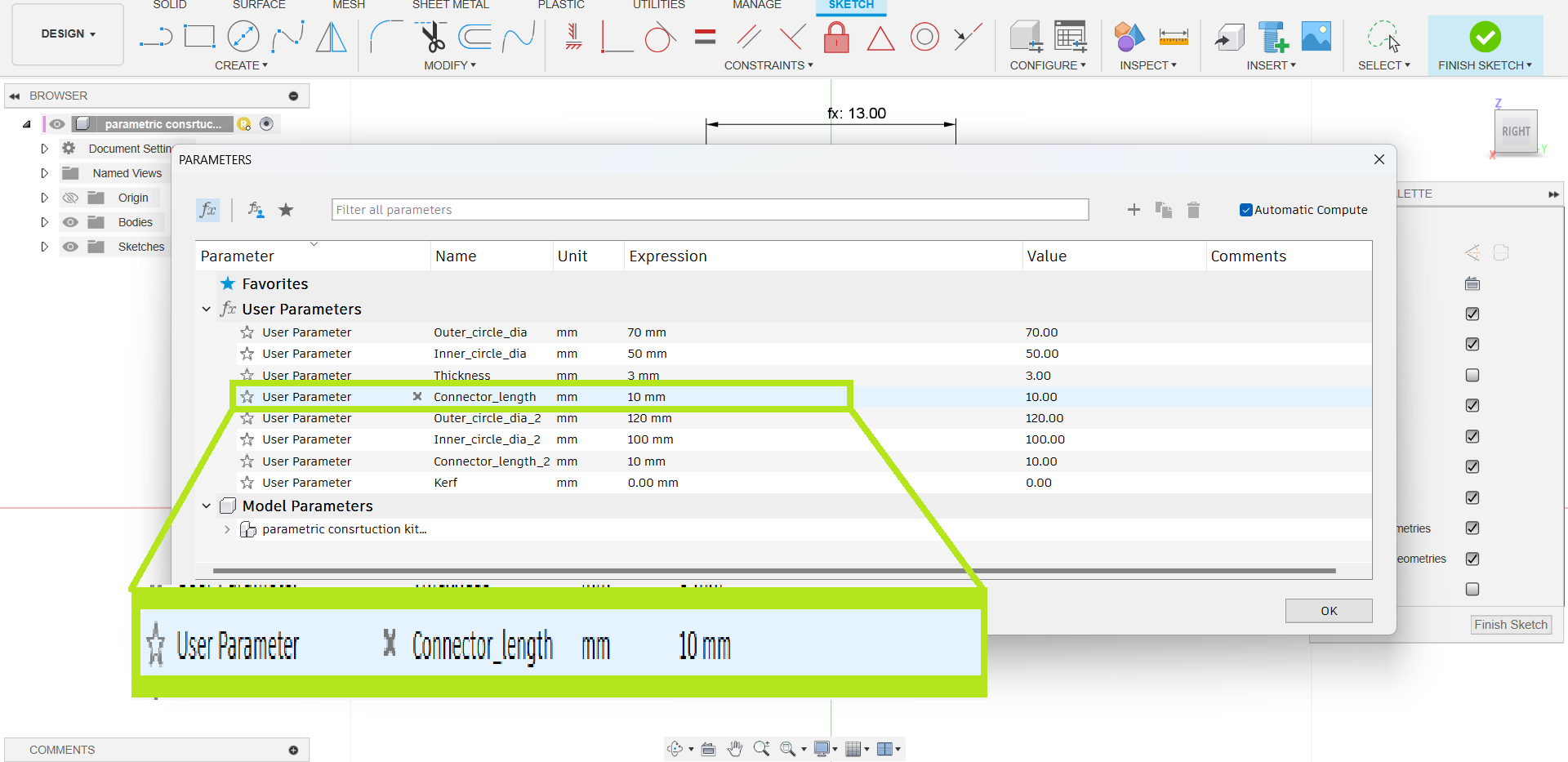
- The image shown below illustrates all the parameters used in my design.
- I checked the construction kit's final result using Fusion's align tool.
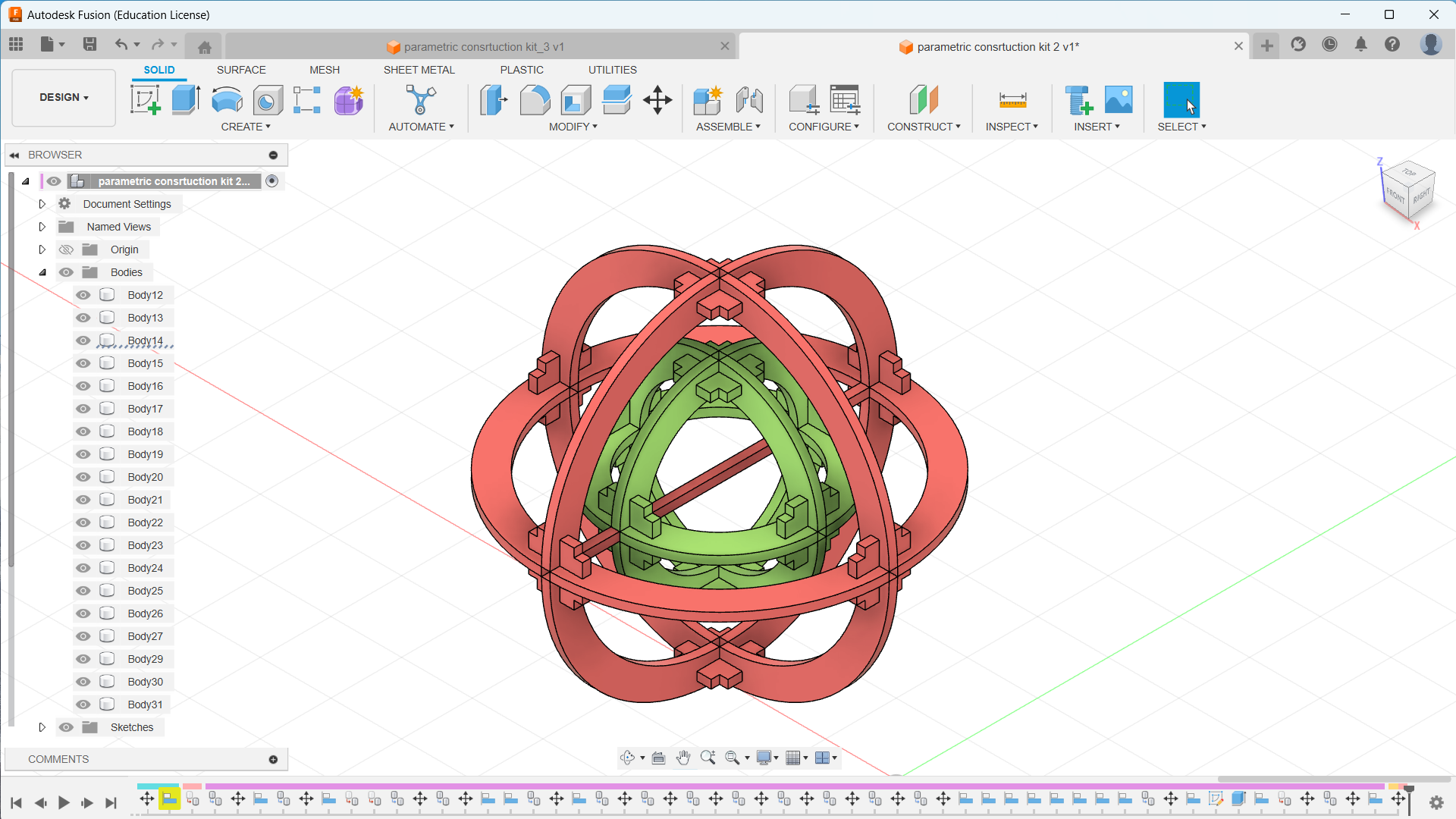
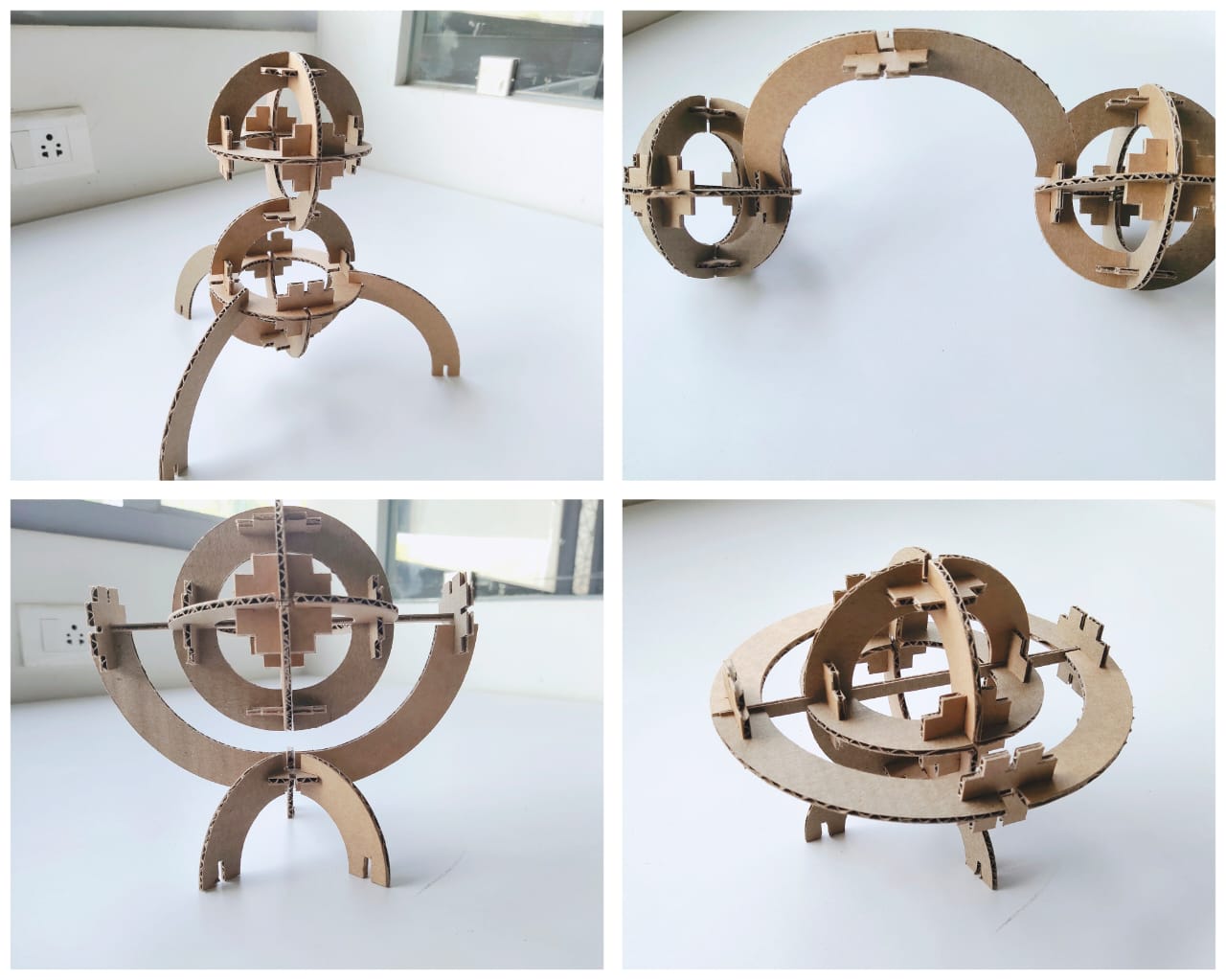
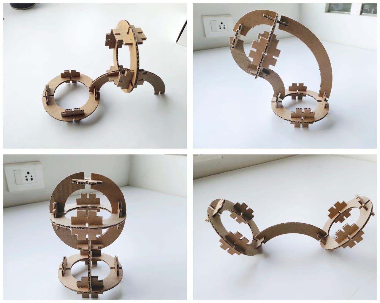
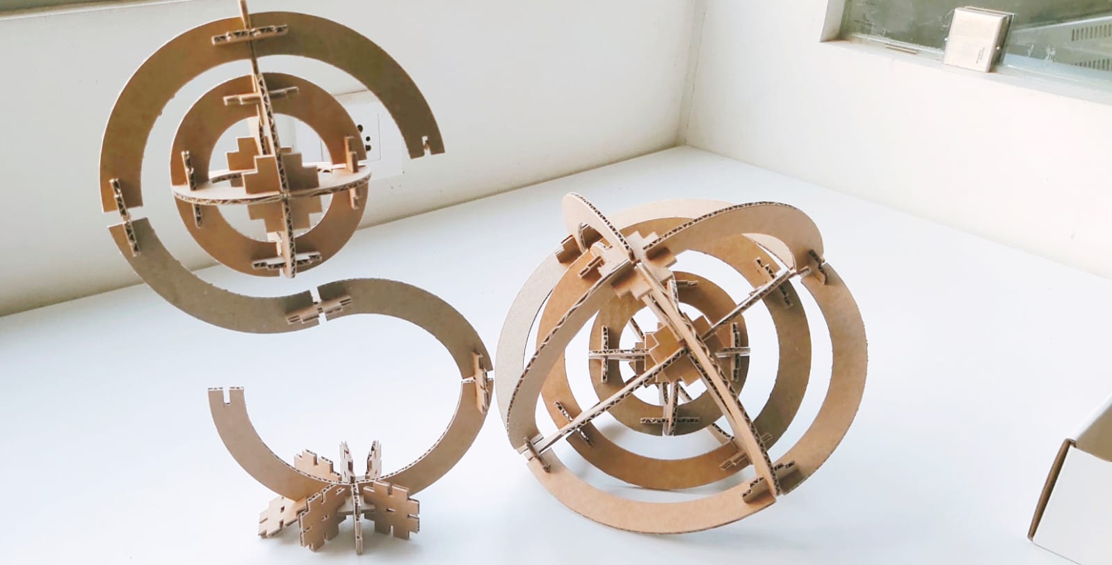
- My intention was to develop a parametric construction kit that can be constructed into many shapes, but I also wanted to create a parametric kit that can be reassembled into a gyroscope.
- This was my first design of the parametric construction kit. Later, after cutting sample parts, it was a perfect fit and successful, but I found out the size of the parametric kit was really small, and I changed the measurement from the parameter settings.
Second Attempt
- The first attempt was not a complete success, so I increased the size of the construction kit by changing the dimensions in the parameter setting.
- The shape of the sketch is automatically altered. This feature is fantastic 😃.
- Once done with the basic sketch, I used the rectangular array to duplicate the basic pieces.
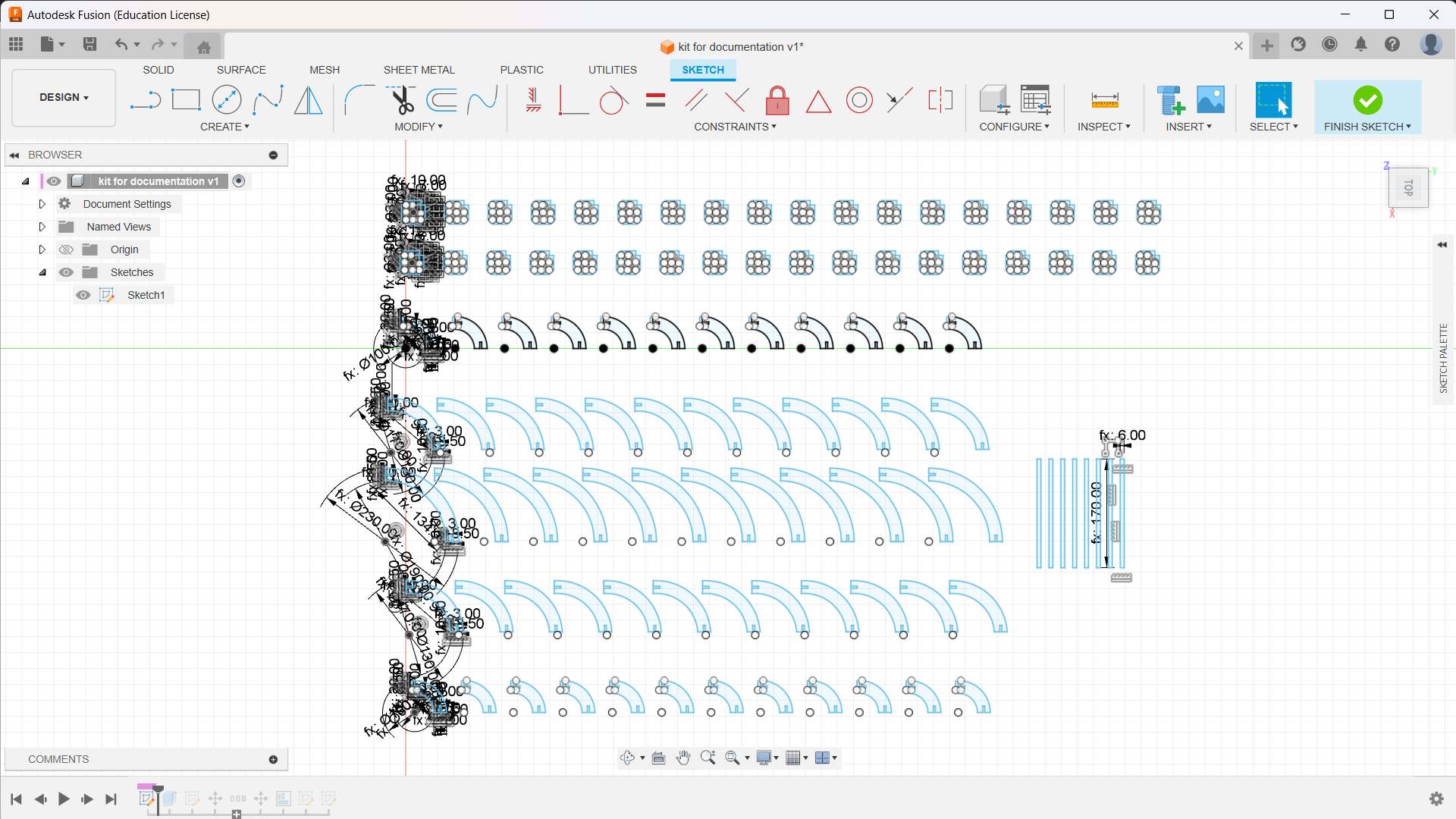
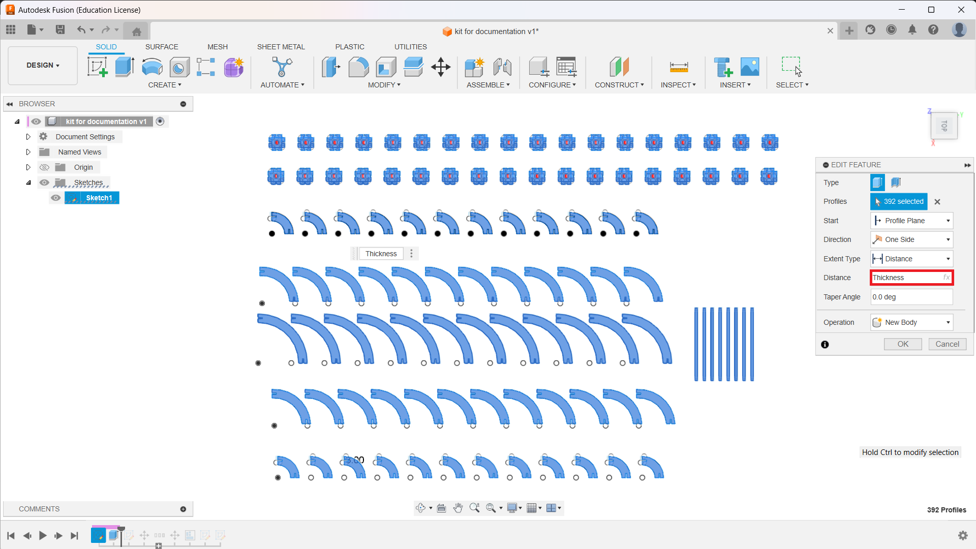
- I extruded the sketch to the thickness of the cardboard.
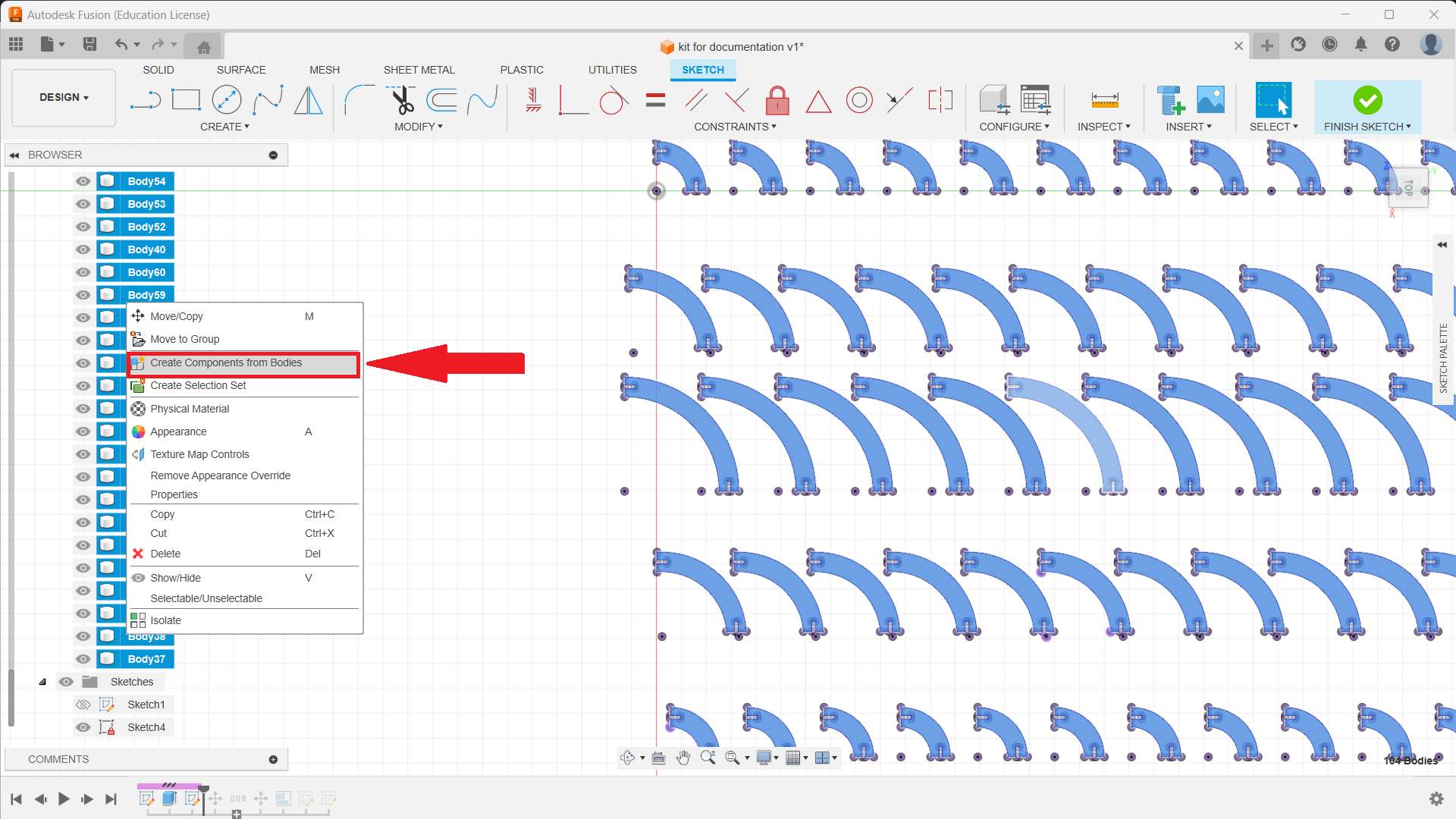
- Once done with extrude, select all the bodies, right click and select “create components from bodies”.
- Create a new assembly file in Fusion 360.
- Insert each component into the assembly.
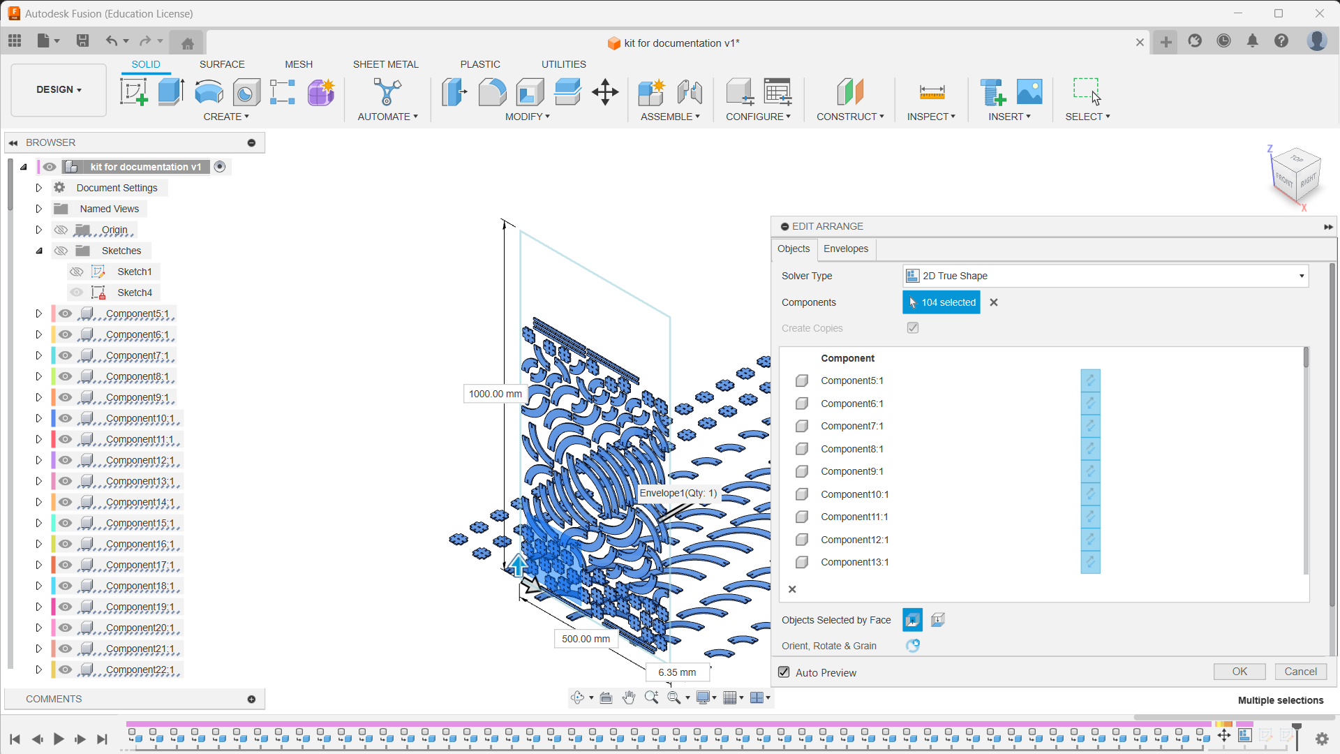
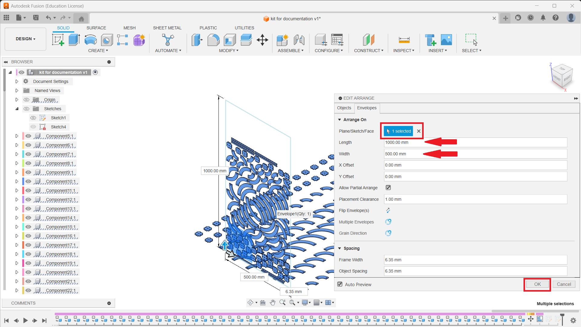
- From the "Envelope”, select a plane that is perpendicular to our sketch. Adjust the length and width of the envelope.
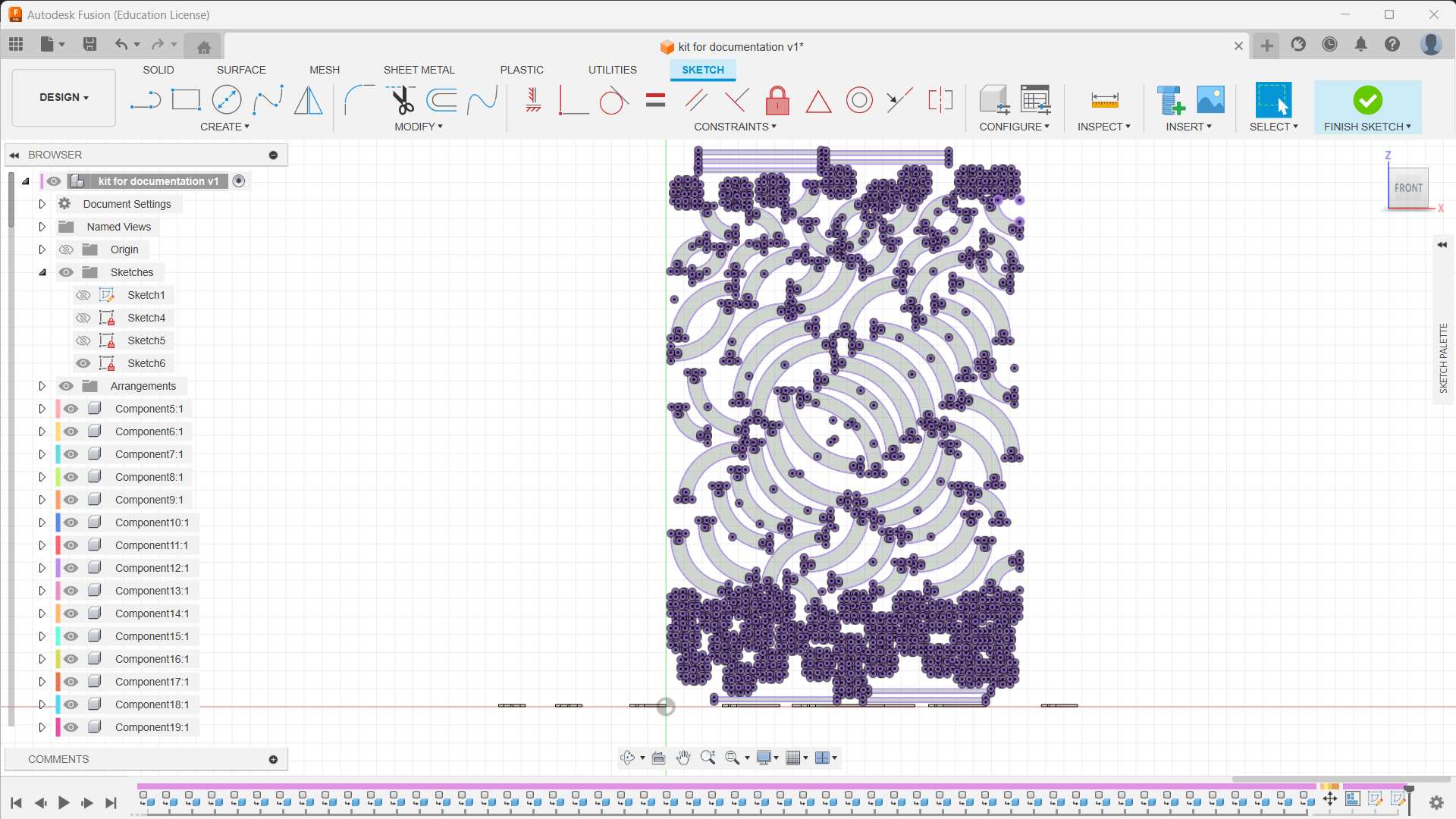
- Create a new sketch and select any of our component faces as the plane. Press “P” for project and select all the faces of the arranged components. Click on Finish Sketch.
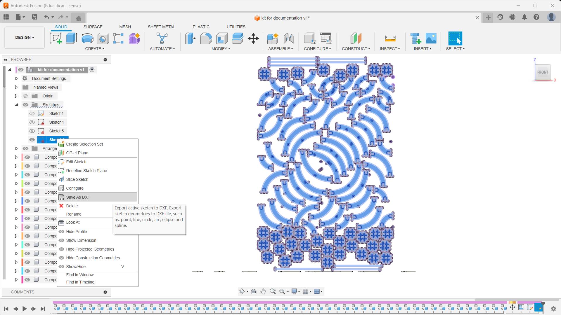
- Select the last sketch, right click, and select “save as DXF”.
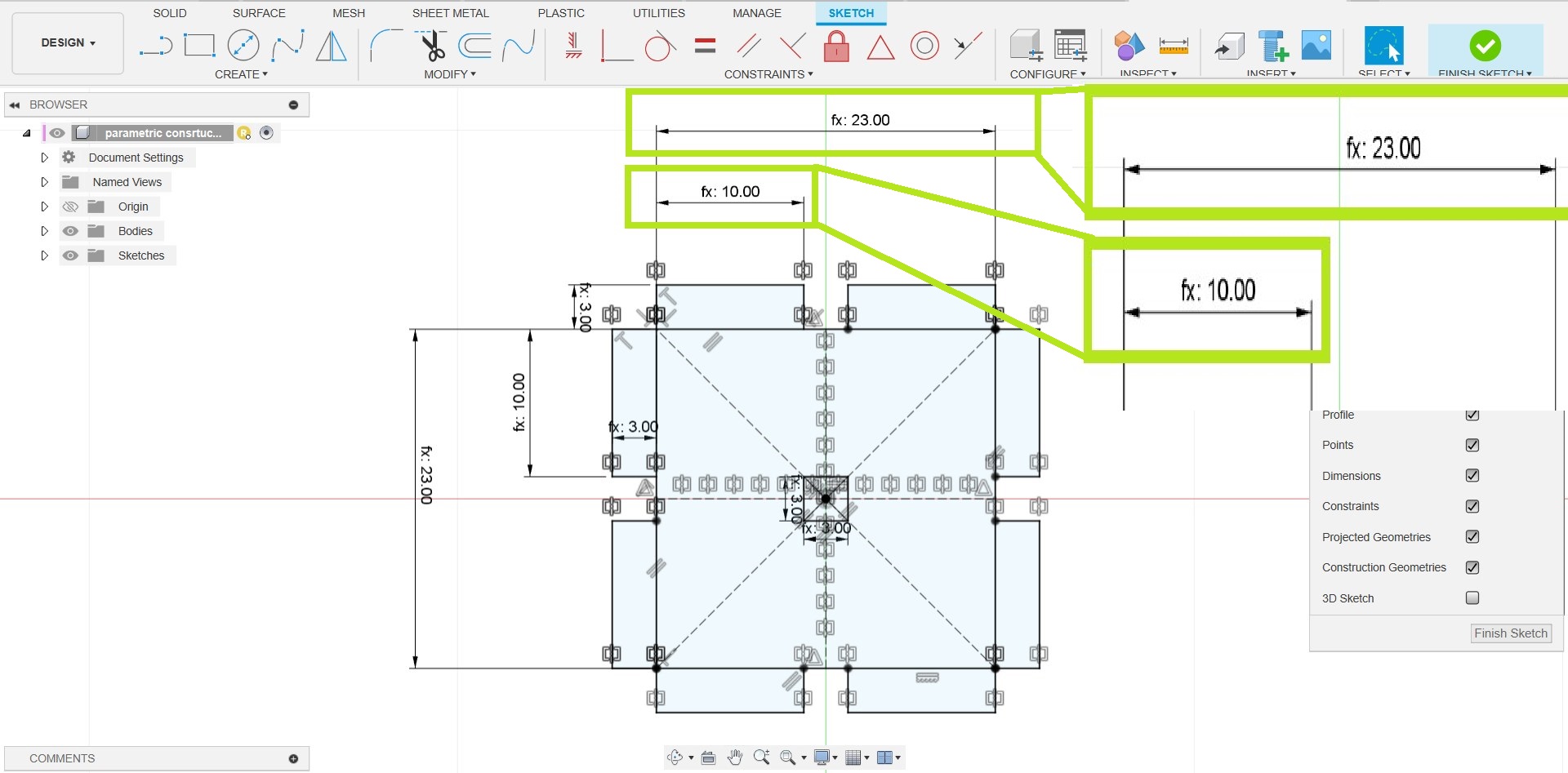
What Happens If I Change the Parameter Value ❓
- Let's check what the purpose of the parametric design is. Assume a situation where I want to build a scaled-up or scaled-down version of the same construction kit. In such a situation, rather than spending my time on designing, I could easily do the job by changing the parameter values.
- In parametric design, I set the connector length as 10 mm and the thickness as 3mm, so the actual length of the connector is connector length + thickness = 13 mm. Every dimension is based on the connector length and thickness value, so if I change the connector and thickness value, it will reflect in the design.
- I decided to change the connector length value from 10mm to 20mm just to see if it worked properly.
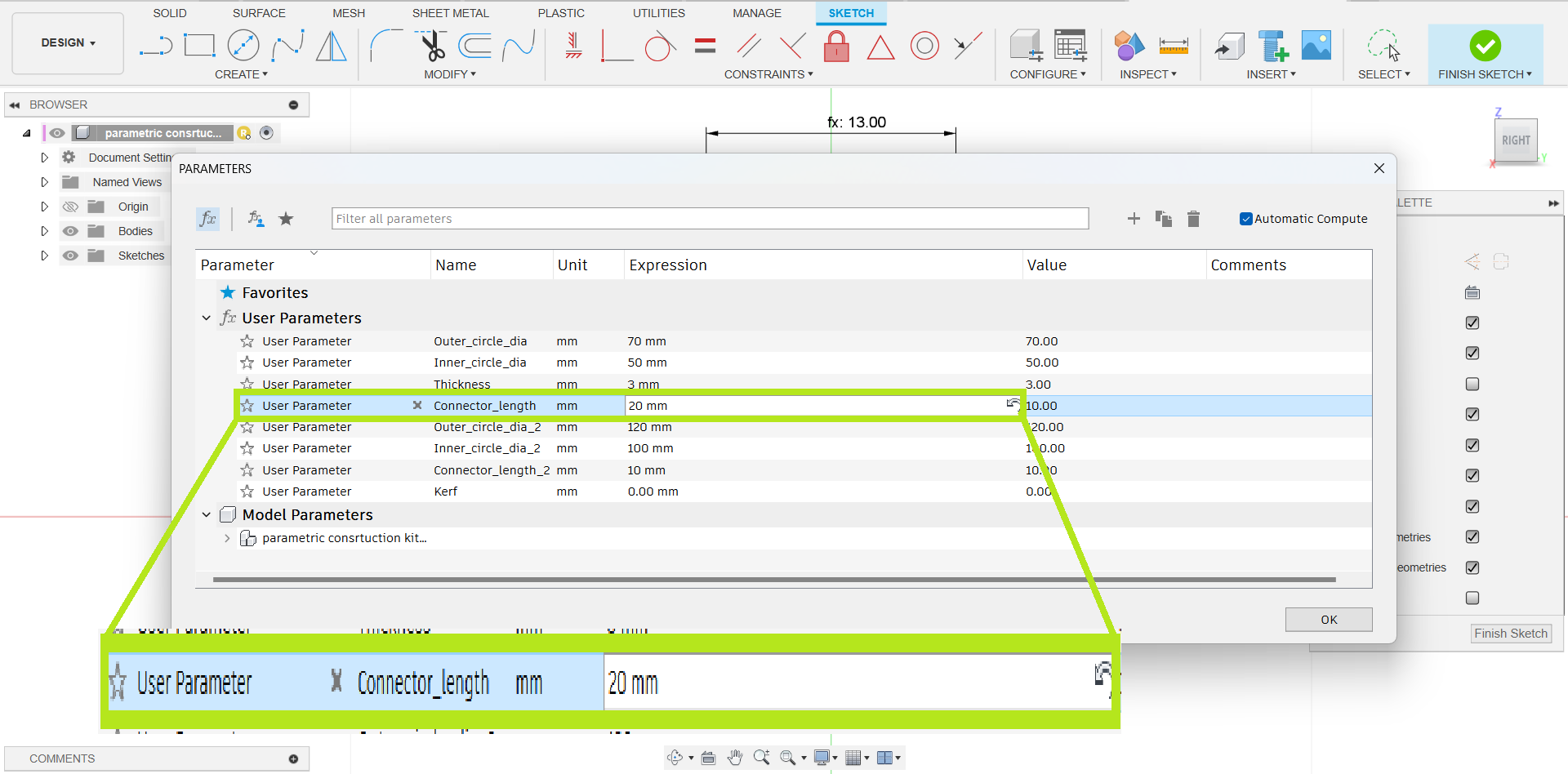
- It worked 😀. The image below illustrates the scaled version of the sketch, in which the actual length of the connector changed from 13 mm to 23 mm.
Machine and Software Setup
- There are three software programs to operate Zund. They are: Cut Editor, Cut Queue, and Cut Centre.
- The Cut Editor is the software component where you design and create your cutting files. It is the interface where you import or create your designs, set up cut paths, and define the cutting parameters.
- The Cut Queue is where you manage and organize your cutting jobs. It acts as a job queue, allowing you to schedule and prioritize different cutting tasks.
- The Cut Centre serves as the central hub for managing the overall cutting production workflow.
- Place your cardboard material on the Zund cutting table.
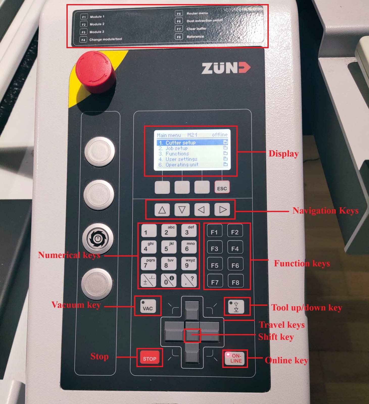
- The photo below depicts an overview of the Zund control panel.
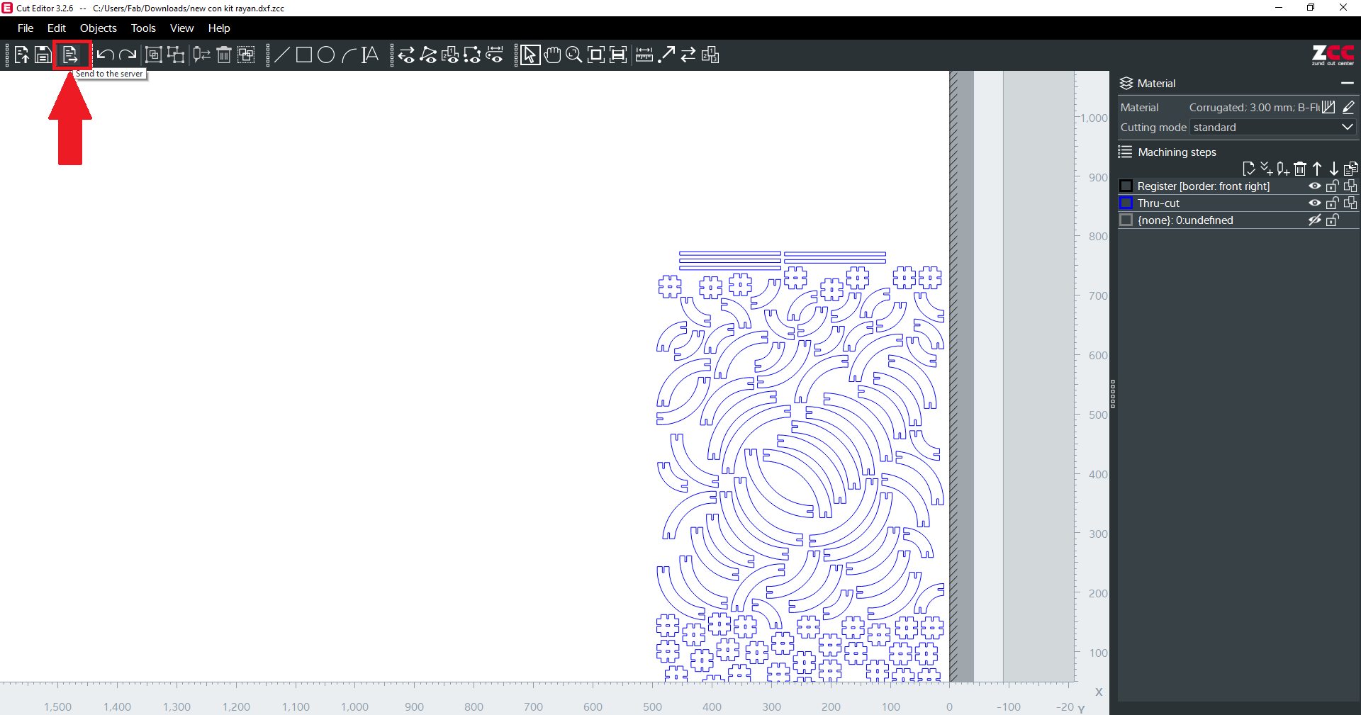
- Right-click the DXF file of our parametric kit and open it with “cut editor”.
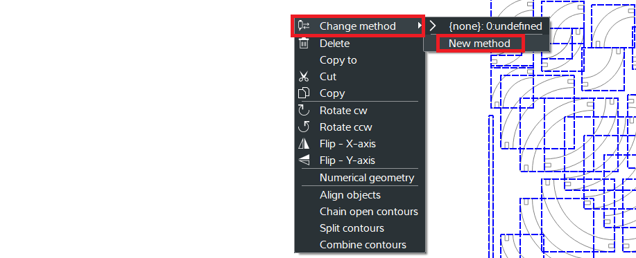
- Right-click and select “Change method", then select “New method”.
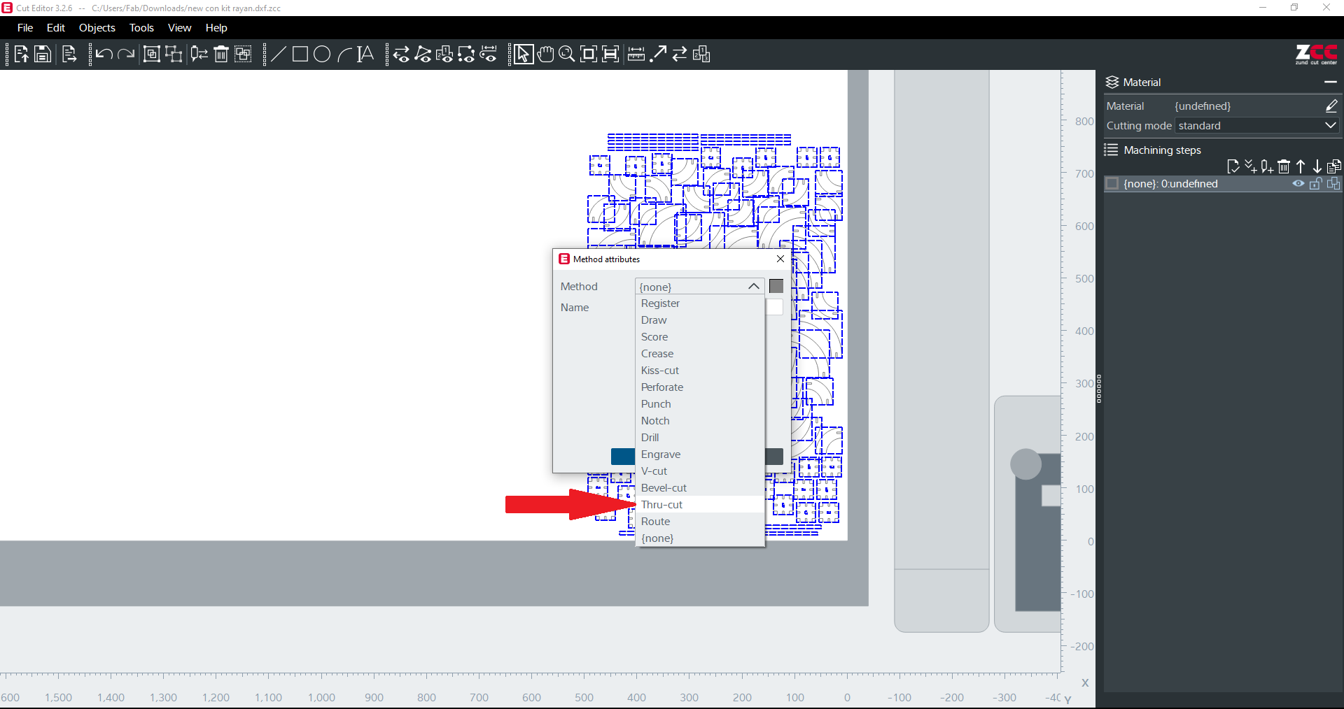
- From the “method attributes”, select “Thru-cut” from the method, and click “OK”.
- Right-click again and select “Change method", then select “New method”.
- Right-click and select “Change method", then select “New method”.
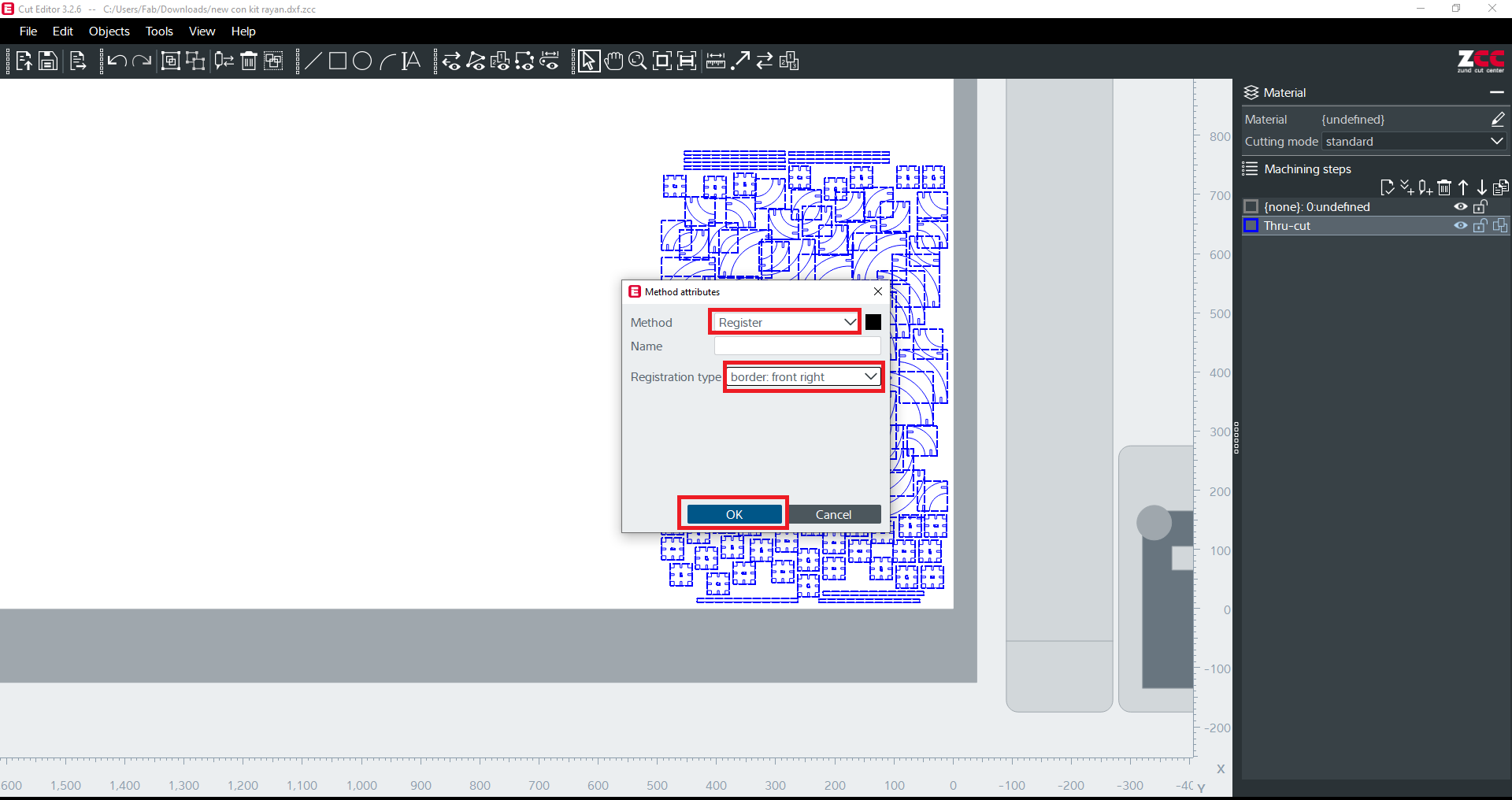
- From the “method attributes”, select “Register”, select “Border: front right” from the method, and click “OK”.
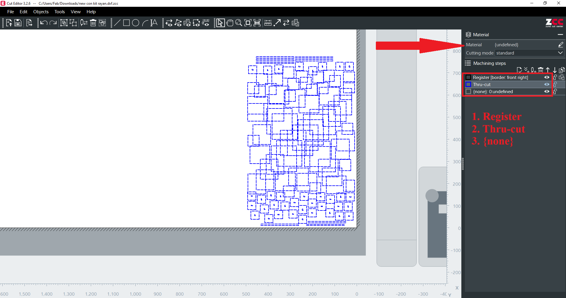
- From the machining steps, rearrange it in such a way that “register” will perform first, then “thru-cut” will perform second.
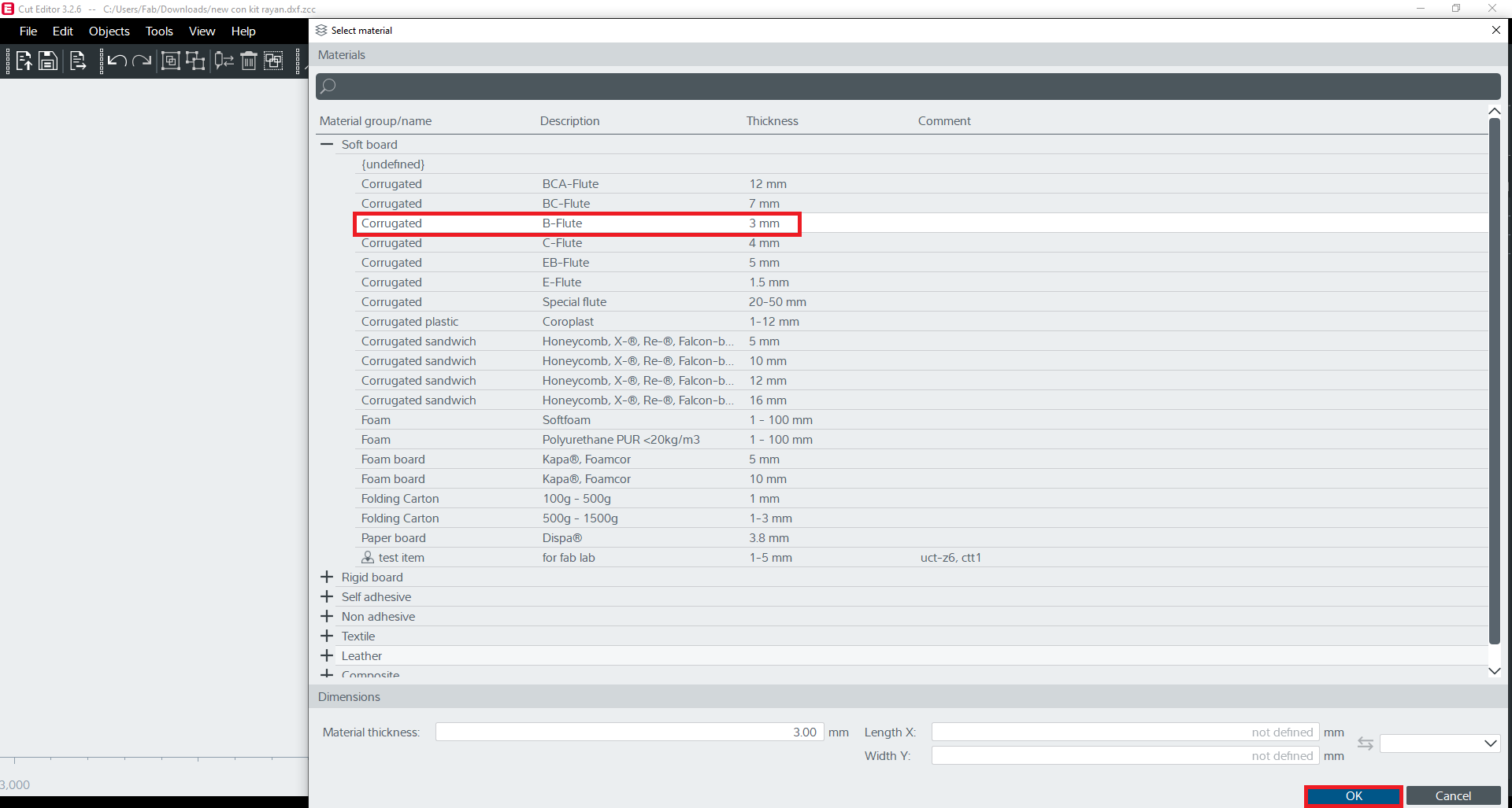
- From the material, select the desired material; in my case, it was cardboard with 3mm, so I selected B-Flute.
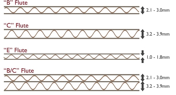
- The figure below shows the pictorial representation of different flutes and their measurements.
- Once done with selecting the material, click on “send to the server”.
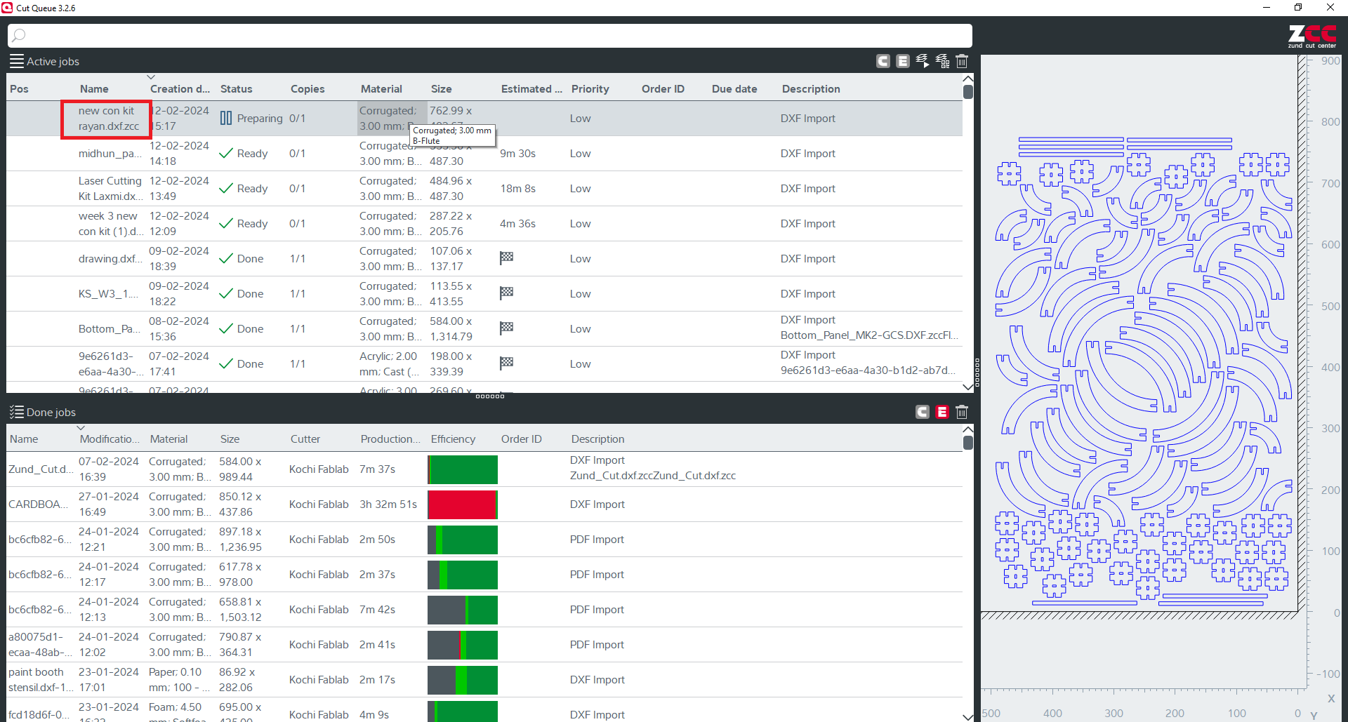
- Close the “Cut Editor” and open “Cut Queue” and double click the our file to proceed further.
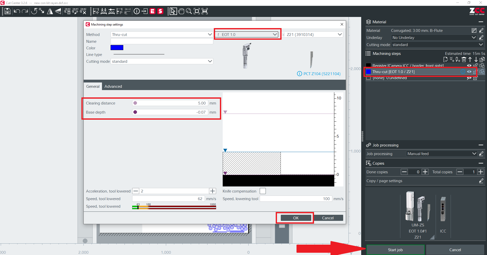
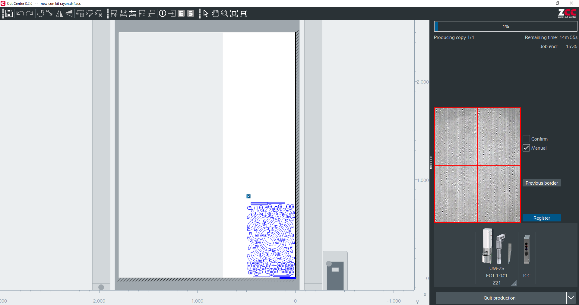
- Close the “Cut Queue” and open “Cut Center”, Double-click “thru-cut” and change the values if needed. Click “Ok” and click “Start Job”.
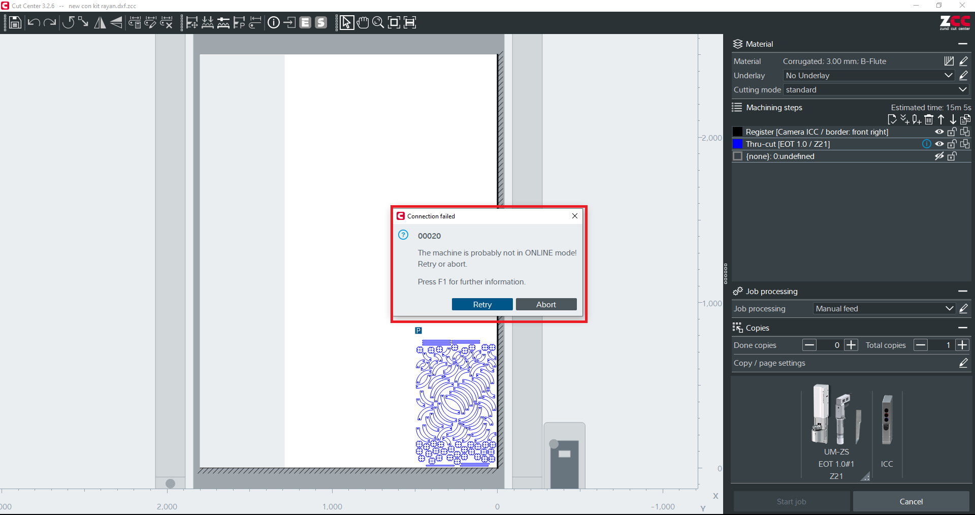
- If the machine is not online, then a message box called “connection failed” will appear. To bring the machine back online, press “Online key” from the control panel.
- Set the edges of our cardboard from the “cut center” with the help of a laser and camera on the zund. Use the arrow keys from the keyboard to move the tool, and when a green line appears, press enter.
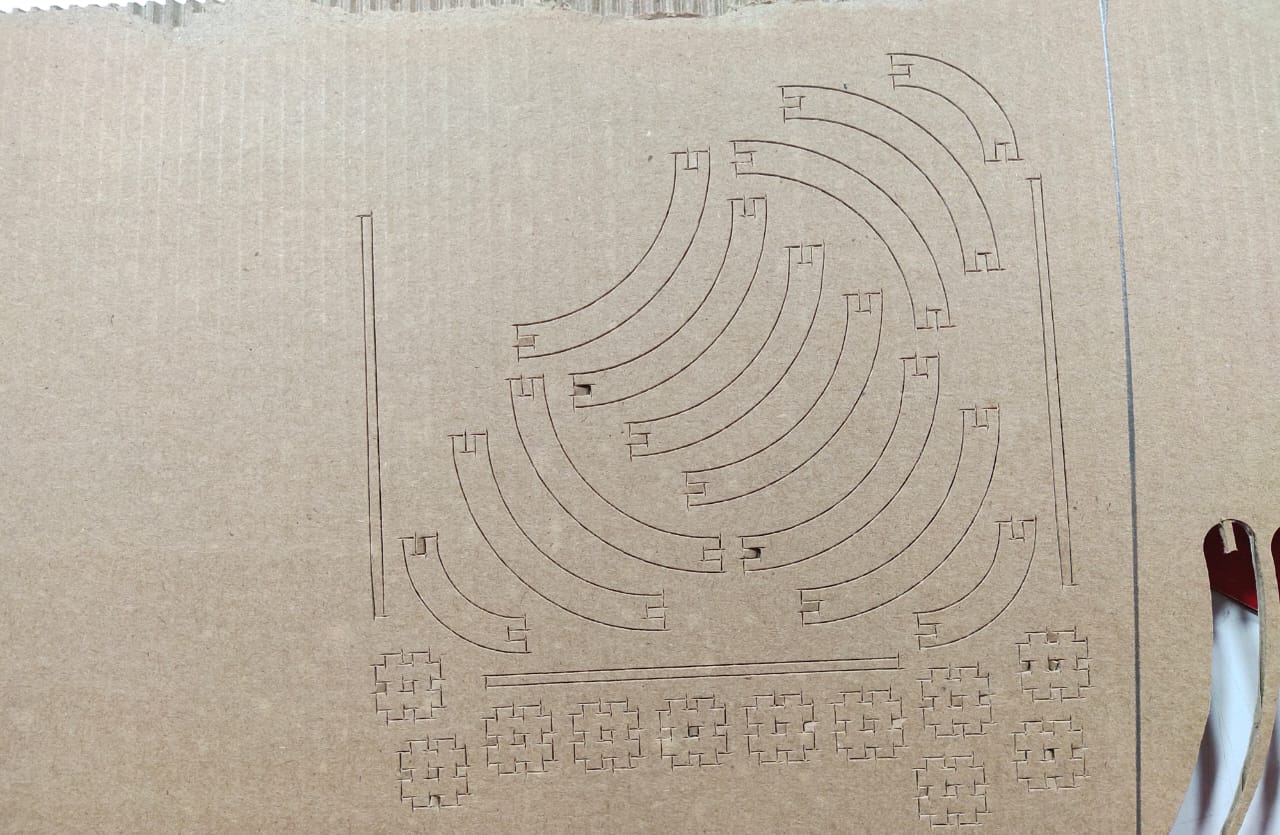
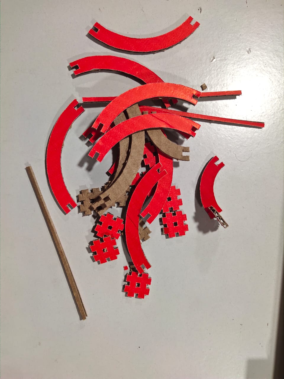
Final Result

Reference
Resources and Downloads
📁 Parametric Construction Kit STL File
📁 Parametric Construction Kit DXF File